7 Golden DFM Rules for Silicone Keypad & Enclosure Integrated Design: Reduce Assembly Steps & Lower Costs
- Share
- publisher
- Suey
- Issue Time
- Jul 14,2026
Summary
The Hidden Cost of Fragmented Assembly: Why Your Silicone Keypad Design Needs a Unified Approach You have a great product concept, but when it hits production, reality strikes. Managing multiple suppliers for keypads, housings, and seals. Aligning parts across multiple assembly stations. Watching tolerance stack-ups eat into your quality margins. Every additional component introduces a failure point — misalignment, contamination, rejected assemblies, delayed shipments. For pr...
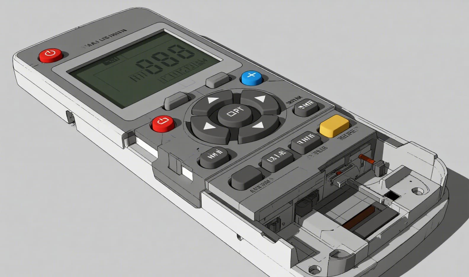
You have a great product concept, but when it hits production, reality strikes. Managing multiple suppliers for keypads, housings, and seals. Aligning parts across multiple assembly stations. Watching tolerance stack-ups eat into your quality margins. Every additional component introduces a failure point — misalignment, contamination, rejected assemblies, delayed shipments. For procurement managers and design engineers in industrial electronics, medical devices, and automotive controls, the traditional "separate keypad + housing + gasket" model is a familiar bottleneck. A silicone keypad that integrates directly with the enclosure isn't just an aesthetic upgrade — it is a strategic manufacturing decision that directly impacts your BOM cost, assembly yield, and time-to-market. This article presents 7 Golden DFM Rules that leading silicone keypad manufacturers use to achieve integrated silicone keypad and enclosure designs — reducing assembly steps by up to 60% and lowering overall project cost by 30–40%. The Problem: Traditional designs require a separate O-ring or gasket between the keypad and the housing to achieve IP65/IP67 sealing. That means one extra part to source, inspect, and assemble — and one more potential leak path. The DFM Solution: Mold a continuous sealing lip directly onto the perimeter of the silicone keypad. This lip compresses against the housing bezel during final assembly, creating an effective environmental seal without any separate gasket. Design Parameters: Impact: Eliminates one SKU, one assembly step, and one potential leak path per product. Typical cost saving: $0.15–$0.40 per unit in gasket material and labor. The Problem: Without built-in alignment features, operators must manually position the keypad relative to the PCB and housing. This visual alignment consumes 3–8 seconds per assembly and introduces a high risk of misalignment — especially in low-light production environments. The DFM Solution: Design positioning ribs on the bottom surface of the keypad that nest into corresponding recesses in the housing (or alignment pins that fit through PCB mounting holes). These features create a mechanical datum that guarantees ±0.1 mm repeatability without human judgment. Design Parameters: Impact: Reduces assembly time from 8 seconds to under 2 seconds per unit. Eliminates rework caused by crooked keypad placement — a common source of 3–5% yield loss in manual assembly lines. The Problem: Non-uniform wall thickness in compression-molded silicone keypads causes differential shrinkage during curing. Thick sections remain hot longer, creating internal stress that manifests as warped keypads, sunken legends, or inconsistent button heights. The DFM Solution: Design the entire keypad web, actuation pads, and mounting flanges within a consistent thickness range. The industry-sweet spot for compression-molded silicone rubber keypads is 0.040″ (1.0 mm) to 0.090″ (2.3 mm). Key Design Rules: Impact: Consistent wall thickness is the single most impactful DFM rule for silicone keypad molding. It directly determines dimensional stability, cosmetic quality, and the repeatability of tactile force across production batches. The Problem: Every undercut in a silicone rubber mold requires a sliding action, lift core, or split insert — adding $3,000–$8,000 per action in tooling cost and increasing per-cycle maintenance time by 15–25%. The DFM Solution: Audit every design feature and ask: "Can this be achieved without an undercut?" Common avoidable undercuts include: When undercuts are truly necessary (e.g., for a locking feature), design them with a draft angle of at least 3° on the undercut face to minimize stripping force. Impact: Eliminating 2 unnecessary undercuts can save $6,000–$16,000 in tooling cost and reduce mold lead time by 2–4 weeks. For a custom silicone keypad project with annual volume of 100,000 units, that translates to a $0.06–$0.16 per-part tooling amortization saving. Unlike rigid plastics, silicone rubber products are flexible enough to be manually or pneumatically stripped from the mold — but that flexibility does not eliminate the need for draft angles. Parts designed with zero draft or negative draft (even unintentionally) experience: Recommended draft angles for silicone keypad molds: Impact: Proper draft angles reduce mold cycle time by 10–15% (faster part removal), extend tool life by reducing abrasive wear during stripping, and eliminate cosmetic defects on the visible keypad surface. This is a zero-cost change that pays dividends across the entire production run. The Problem: Backlit keypad designs traditionally require separate light guide films, light- blocking gaskets, and individual LED housings. Each additional component adds assembly complexity, supply chain risk, and light leakage points that compromise the user experience. The DFM Solution: Integrate both the light-guiding and light-blocking functions directly into the silicone keypad geometry: Key Design Parameters: Impact: Eliminates 2–3 separate components per keypad assembly. Simplifies PCB layout (no need for individual LED shrouds). Achieves more uniform backlighting because the light path is fully controlled within a single molded part. The Problem: Symmetric keypad assemblies can be installed backwards or rotated 180°, causing conductive pills to misalign with PCB contacts. This is one of the most common field failures identified during functional testing — and it is entirely preventable. The DFM Solution: Apply Poka-Yoke (mistake-proofing) principles to the keypad geometry: Impact: Zero-cost design change (no additional features, just repositioned existing geometry). Eliminates a whole class of assembly defects — typically reducing functional test failures by 2–4%. For a medical device application, this can be the difference between passing and failing an FDA design review. The following table compares the traditional fragmented approach with an integrated DFM-optimized design based on a typical industrial control panel with 12 keys, annual volume of 50,000 units: Background: A European industrial automation company approached us with an existing handheld controller design that used a separate silicone keypad, a silicone gasket, and a two-piece ABS housing assembled with 6 screws. Their production line was struggling with 15% rework rates — most caused by keypad misalignment, gasket displacement, and screw over-torquing that deformed the seal. DFM Review & Redesign: Our engineering team applied all 7 Golden DFM Rules to create an integrated design: Results: This case demonstrates that silicone keypad manufacturing with integrated DFM principles is not just a cost-saving exercise — it is a quality transformation that touches every aspect of the product lifecycle. A: For qualified OEM projects, we provide a complimentary DFM review within 2–3 business days of receiving your 3D CAD files (.STEP or .IGES). Our engineers evaluate wall thickness, draft angles, undercuts, parting line locations, and sealing geometry — and deliver a written DFM report with specific recommendations. Submit your design files for a free DFM analysis. A: Rapid prototyping for silicone keypad tooling typically takes 2–3 weeks from DFM approval. For existing tool designs or simple geometry modifications, we can deliver functional samples in as little as 10 working days. Full production tooling (hardened steel, 500k+ cycle life) requires 4–6 weeks. A: We accept .STEP, .IGES, .STL, and .SLDPRT formats, along with 2D drawings in PDF or DWG. For best results, include a complete assembly drawing showing the keypad, housing, PCB, and any sealing interfaces so our DFM review captures all interaction points. A: Absolutely. We offer flexible mold solutions ranging from aluminum prototype tooling (50,000-cycle life, ideal for low-volume or pilot runs) to multi-cavity hardened steel tooling for high-volume production. Our minimum order quantity starts at 500 units for standard designs. A: Our silicone keypad manufacturing facility is ISO 9001:2015 certified. We also comply with RoHS and REACH requirements for material safety. For medical device applications, we can provide full material traceability and biocompatibility documentation upon request. The 7 Golden DFM Rules presented here are proven across hundreds of production programs — from medical handhelds to automotive control panels to industrial HMIs. Each rule addresses a specific manufacturing pain point and delivers measurable improvements in cost, quality, or cycle time. The most cost-effective time to apply these rules is before tooling is cut. A single design-for-manufacturability review at the concept stage can save 10–20× the cost of a post-tooling mold modification. If you are developing a product that uses a custom silicone keypad, we invite you to put our engineering team to the test. Submit your design files and receive a comprehensive DFM report — no obligation, just practical engineering feedback that helps you build a better product. Receive a professional DFM report within 2–3 business days. No obligation, no hidden fees. Or learn more about our silicone keypad manufacturing capabilities and how we help clients transition from fragmented assembly to integrated, cost-optimized designs.The Hidden Cost of Fragmented Assembly: Why Your Silicone Keypad Design Needs a Unified Approach
1. Integrated Sealing Lip — Eliminate Separate O-Rings
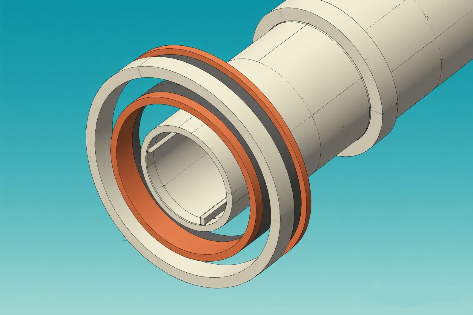
2. Positioning Ribs and Pins — Eliminate Manual Alignment

3. Uniform Wall Thickness — Prevent Warpage and Sink Marks

4. Avoid Unnecessary Undercuts — Reduce Mold Complexity by 30%
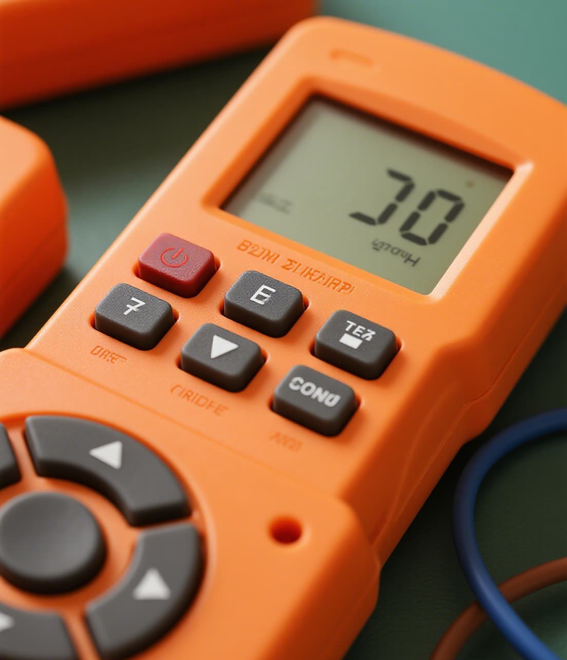
5. Reserve Draft Angles of 1°–3° — Ensure Smooth Demolding
6. Built-in Backlight Management — Integrated Light Barrier and Light Guide
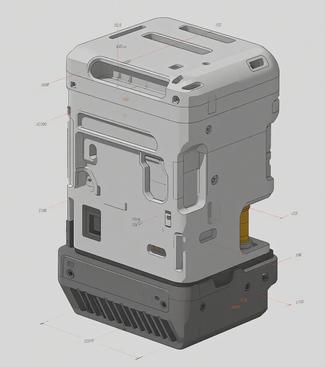
7. Poka-Yoke Design — Asymmetric Positioning Prevents Reversal
Cost-Benefit Analysis: Fragmented vs. Integrated Silicone Keypad Design
Cost Category
Fragmented (Separate Parts)
Integrated (DFM Optimized)
Saving
Number of parts (keypad, housing, gasket, light guide)
4+
1–2
50–75% fewer parts
Mold tooling investment (total)
$28,000–$45,000
$18,000–$28,000
35–38% savings
Assembly steps per unit
12
4–5
58–67% reduction
Assembly labor cost per unit
$1.20–$1.80
$0.40–$0.60
65–67% savings
Supplier management overhead
3–4 suppliers
1 supplier
Single-source accountability
First-pass yield (assembly)
85–90%
96–98%
+8–13% yield gain
Per-unit total cost (tooling amortized)
$4.50–$6.80
$2.70–$3.90
40–43% cost reduction
Real Case: Industrial Controller — From 12 Steps to 4, Yield from 85% to 97%
Frequently Asked Questions About DFM for Silicone Keypads
Q: Is DFM analysis free? Do you charge for design review?
Q: What is the fastest turnaround for a prototype?
Q: What file formats do you accept for DFM review?
Q: Can you handle small batch quantities (1,000–5,000 units/year)?
Q: What certifications does your factory hold?
Ready to Optimize Your Silicone Keypad Design?