8 Most Common Silicone Keypad Mold Design Mistakes Engineers Make (And How to Fix Them)
- Share
- Issue Time
- Jul 6,2026
Summary
Learn the 8 most common DFM mistakes in silicone keypad mold design — including draft angles, wall thickness, corner radii, conductive pill alignment, shrinkage, parting line placement, spacing, and sealing. Includes technical specifications, tolerance tables, and a real-world case study showing how DFM review saved $12,000 in mold rework.
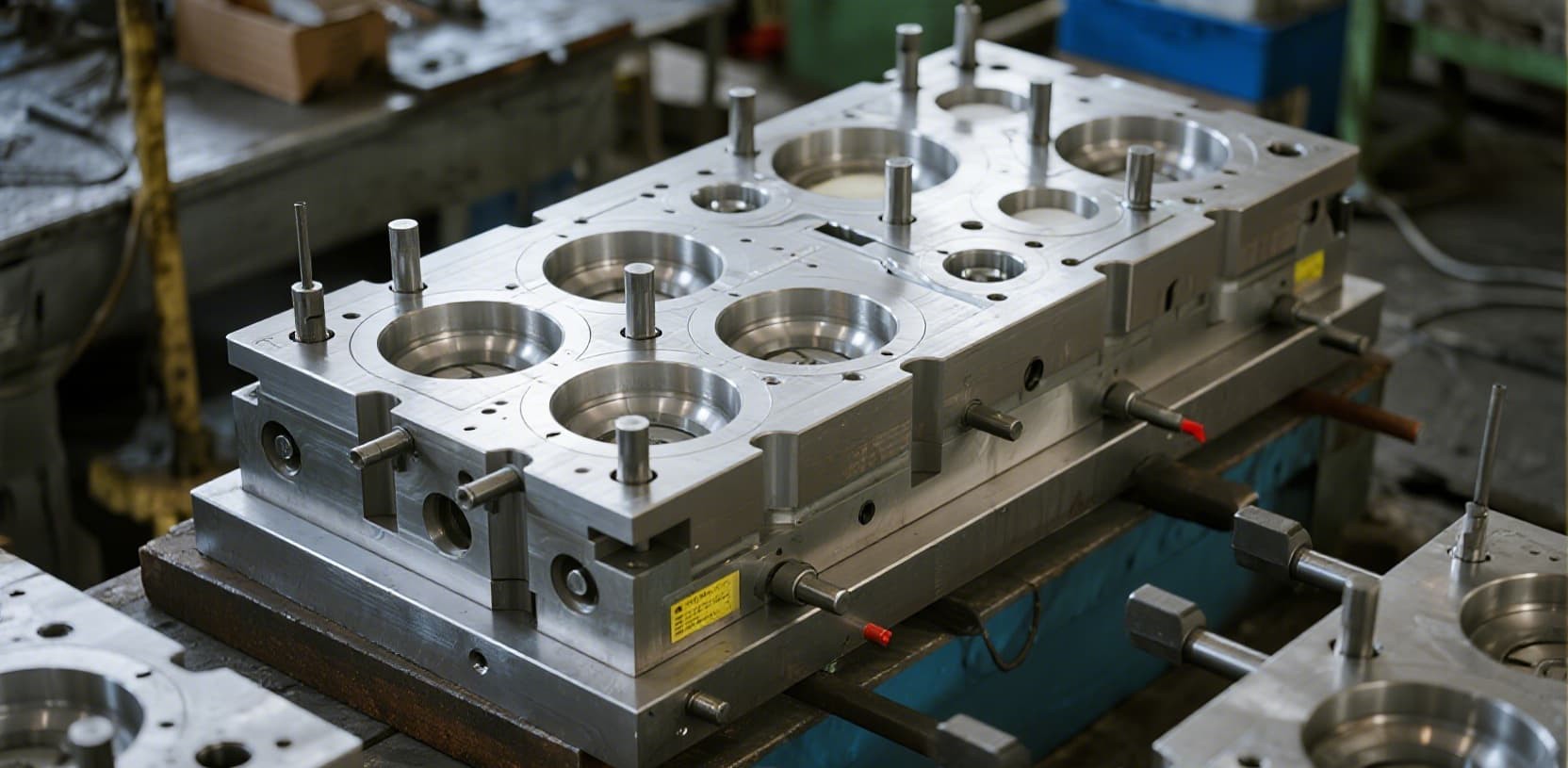
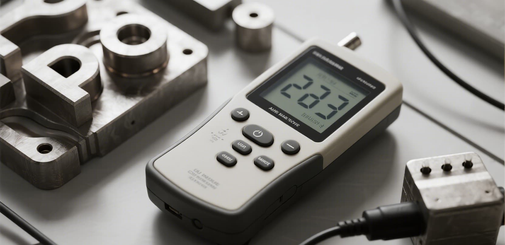
A well-executed Design for Manufacturability (DFM) review can save up to 40% in tooling costs and prevent months of production delays. You have designed what you believe is a perfect silicone keypad. The CAD file looks clean, the dimensions are exactly right, and the client has signed off. Then the mold maker calls: "This design cannot be molded as is. We need to modify the draft angle, adjust the wall thickness, and redesign the corner radii." The result? A $5,000 unexpected tooling revision and a three-week project delay. This scenario plays out every day in the silicone keypad industry. The root cause is almost always the same: design decisions made without considering manufacturability constraints. In this guide, we walk through the 8 most common DFM mistakes in silicone keypad mold design, explain the engineering principles behind each one, and show you how to fix them before your design reaches the mold maker. The draft angle is the tapered angle applied to the vertical walls of a keypad mold to facilitate part ejection after compression molding. When this angle is too small — or absent entirely — the cured silicone rubber cannot release cleanly from the mold cavity. Industry practice requires a minimum draft angle of 1 degree for keys under 0.200 inches (5.08 mm) tall and 2 degrees for keys exceeding 0.500 inches (12.7 mm). For deep-drawn features or textured surfaces, a draft of 3 to 5 degrees is recommended. Silicone rubber, unlike rigid plastics, does not flow evenly through variable-thickness channels during compression molding. When your keypad design has abrupt transitions between thick and thin wall sections, the material cures at different rates, creating internal stresses and dimensional inconsistencies. Sharps corners are the enemy of silicone molding. When a design specifies 90-degree internal corners or razor-sharp edges, the silicone compound cannot flow into the corner, trapped air creates voids, and stress concentration leads to premature tearing at the corner during demolding. Minimum internal radius: 0.010 inches (0.25 mm). For external corners, a radius of 0.015 to 0.020 inches is preferred. Deep pockets and cavities require a minimum of 0.020 inches. These values are not arbitrary — they are derived from the flow characteristics of liquid silicone rubber (LSR) and the mechanical stress distribution during demolding. The parting line is where the two halves of the compression mold meet. Its placement directly affects flash formation, surface finish, and the ease of deflashing after molding. A poorly placed parting line creates visible witness lines on the keypad surface and makes secondary trimming difficult. The conductive pill (carbon or gold contact) is the bridge between the silicone keypad and the PCB. When the pill location does not align precisely with the PCB contact pad, the keypad fails to register keystrokes consistently — a direct cause of field failures and customer complaints. During the DFM review, the conductive pill location must be verified against the PCB layout. A common mistake is designing the pill position based on the keypad drawing alone without cross-checking the PCB land pattern. The result is a ±0.3 mm mismatch that causes intermittent contact. Silicone rubber shrinks by 2-5% during the cooling phase after molding (linear shrinkage). This shrinkage is not isotropic — it varies with wall thickness, key geometry, and material formulation. Designs that ignore shrinkage produce keypads that are undersized and fail to fit the enclosure. The industry standard for silicone molded parts is ISO 3302 Class M1, which defines permissible dimensional deviations based on nominal size. Here is a quick reference: Key spacing is frequently overlooked, yet it directly impacts user experience. When keys are too close together, users accidentally press adjacent buttons (ghosting). When spacing is inconsistent, the keypad looks and feels unprofessional. A keypad that performs perfectly in the lab may fail within weeks in the field if its design does not account for environmental exposure. Moisture ingress, dust accumulation, chemical exposure, and UV degradation are common failure modes that trace back to design decisions. A European manufacturer of air quality monitoring devices approached us with a custom silicone keypad design for their new industrial-grade product. The original design specified: During our DFM review, we identified four critical issues: insufficient draft angle (0.5° vs. required 2°), abrupt wall thickness transition, missing corner radii on internal features, and a 0.3 mm pill-to-PCB mismatch. By catching these issues before mold fabrication, the client avoided an estimated $12,000 in mold rework costs and 6 weeks of production delay. The revised design achieved a first-article approval rate of 98% and passed 1 million cycle life testing. Before sending your silicone keypad design to the mold maker, run through this checklist: The industry minimum is 1° for standard keys under 0.200 in (5 mm) tall. Keys taller than 0.500 in (12.7 mm) require at least 2° draft. For deep cavities or textured surfaces, 3-5° is recommended to prevent tearing during demolding. Silicone rubber exhibits 2-5% linear shrinkage after molding, with most compounds shrinking between 2.5-3.5%. The exact rate depends on material formulation, wall thickness, and cure temperature. Always request a shrinkage compensation analysis from your mold maker. ISO 3302 Class M1 is the standard specification for precision silicone molded parts. For a 25 mm dimension, this allows ±0.13 mm. Avoid specifying tighter tolerances than necessary, as this increases mold cost without functional benefit. Yes, most reputable silicone keypad manufacturers, including FromRubber, offer complimentary DFM analysis for new designs. Simply submit your 2D drawing or 3D model, and the engineering team will review it for manufacturability, identify potential issues, and provide optimization recommendations. Minimum internal radius is 0.010 inches (0.25 mm). For deep cavities and pockets, 0.020 inches (0.50 mm) is preferred. Never design sharp 90-degree internal corners in silicone molds. The difference between a smooth production launch and a costly mold rework often comes down to a handful of design decisions made early in the project. By understanding and avoiding these 8 common DFM mistakes, you can: At FromRubber (Bohao Electronics), our engineering team has conducted over 500 DFM reviews for silicone keypad designs across industries including medical, automotive, industrial, and consumer electronics. With 16 years of precision molding experience, we help clients identify and resolve manufacturability issues before a single mold cavity is cut. Ready to move your silicone keypad design from concept to production? Submit Your Design for Free DFM Analysis We typically respond within 24 hours with a detailed DFM report and a no-obligation quotation.8 Most Common Silicone Keypad Mold Design Mistakes Engineers Make (And How to Fix Them)
Mistake #1: Insufficient Draft Angles

The Technical Standard
What Happens When You Ignore It
Mistake #2: Uneven Wall Thickness
Recommended Parameters
Parameter
Recommended Range
Impact
Mat thickness
0.040 - 0.150 in (1.0 - 3.8 mm)
Force profile & durability
Key web thickness
0.008 - 0.020 in (0.2 - 0.5 mm)
Tactile feel & snap ratio
Wall transition ratio
3:1 max (thick:thin)
Flow consistency
Minimum corner radius
0.010 in (0.25 mm)
Stress concentration
Consequences of Poor Wall Design
Mistake #3: Incorrect Corner Radii (R-Corners)
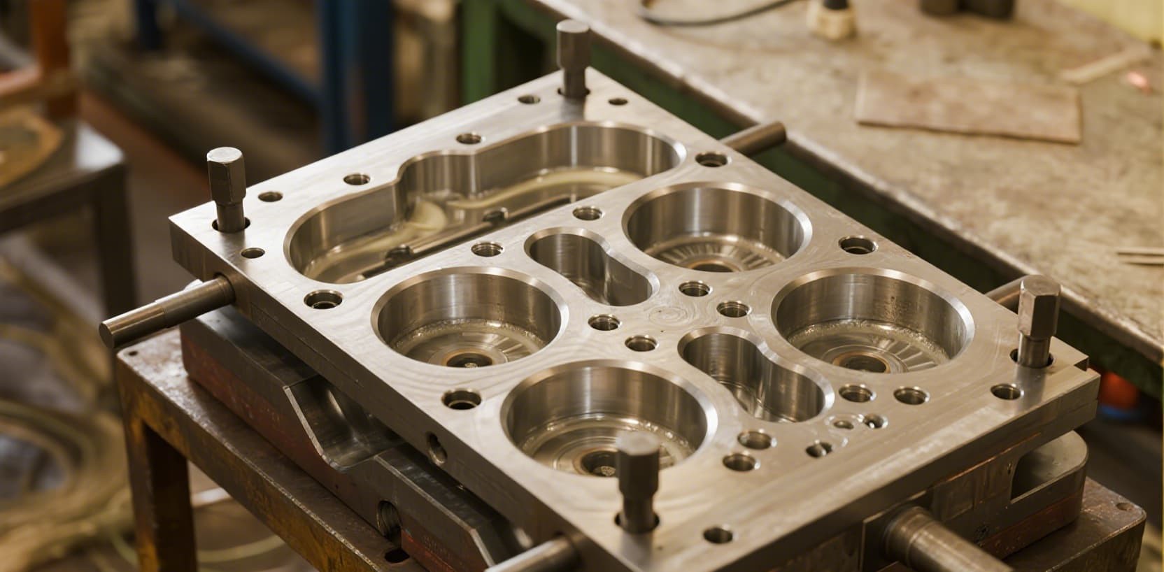
Engineering Requirement
Mistake #4: Poor Parting Line Placement
Critical Design Rules
Mistake #5: Misaligned Conductive Pill Placement
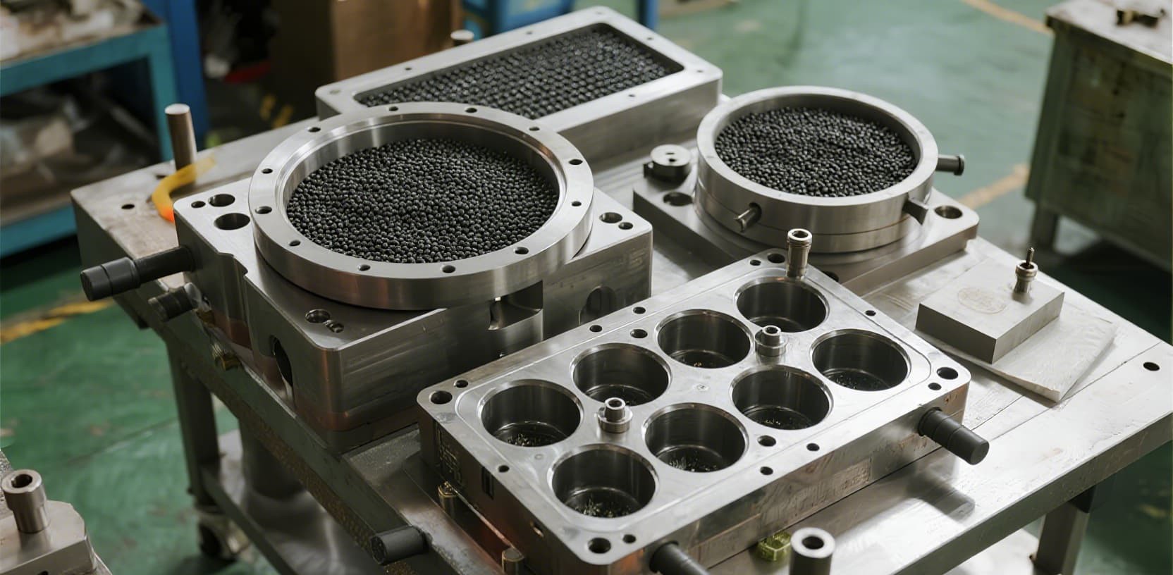
Alignment Tolerances
DFM Requirement
Mistake #6: Ignoring Silicone Shrinkage and Tolerance Class
Tolerance Standards
Nominal Dimension
Class M1 Tolerance
0 - 25 mm
±0.13 mm
25 - 37 mm
±0.20 mm
37 - 50 mm
±0.25 mm
50 - 62 mm
±0.31 mm
62 - 75 mm
±0.38 mm
75 - 100 mm
±0.50 mm
Mistake #7: Oversized Keys Without Adequate Spacing
Recommended Spacing Guidelines
Mistake #8: Neglecting Environmental Sealing Requirements

Design Considerations by Environment
Environment
Sealing Requirement
Material Spec
Consumer indoor (remote controls)
Basic dust seal
Standard silicone, 50-60 Shore A
Medical devices
IP54, cleanable surface
FDA-grade silicone, 60-70 Shore A
Industrial / outdoor
IP65-IP67
UV-stabilized silicone, 60-70 Shore A
Automotive
IP67, −40°C to +150°C
High-temp silicone, 65-75 Shore A
Marine / underwater
IP68, salt-spray resistant
LSR, 65-70 Shore A
Real-World Case Study: How DFM Review Saved $12,000 in Mold Rework
DFM Design Checklist: Your Pre-Submission Review
Frequently Asked Questions
What is the ideal draft angle for a silicone keypad mold?
How much does silicone shrink after molding?
What tolerance class should I specify for silicone keypads?
Can I get a free DFM analysis for my silicone keypad design?
What is the minimum corner radius for silicone keypad molds?
Summary: Design Right the First Time