A Guide to Plastic Enclosure Manufacturing: Injection Molding Process
- Share
- publisher
- Suey
- Issue Time
- Nov 18,2025
Summary
Plastic enclosure manufacturing is decided in five places: wall sections, gate position, cooling, ejection and the inspection plan. This guide walks the injection moulding sequence for an enclosure, shows which decisions are still free after tooling and which are not, and sets out what a first-article report should contain.

Process walkthrough
Most of what goes wrong in plastic enclosure manufacturing is decided on the drawing, not on the press. Wall thickness sets the cycle, the gate sets the weld line, cooling sets the warp and ejection sets the marks. By the time the tool is cut, four of those five are frozen — which is why a DFM review before steel is the cheapest hour in the project.
- Wall thickness drives cycle time roughly with the square of the section: a 3 mm wall takes far more than twice the cooling of 1.5 mm.
- Gate position dictates where the weld line lands, and a weld line on a sealing land is a leak.
- Warp is a cooling problem before it is a material problem; balanced cooling beats a stiffer grade.
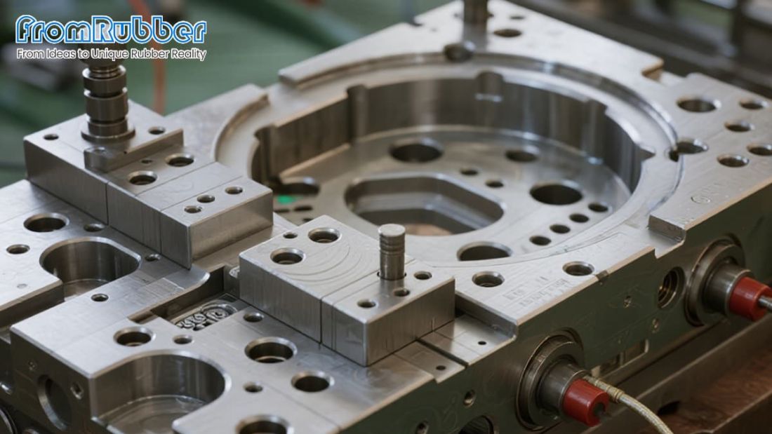
Wall sections and ribs in plastic enclosure manufacturing
An enclosure needs stiffness, and stiffness comes from geometry far more cheaply than from thickness. A 2 millimetre wall with 1 millimetre ribs at a 2.5 to 3 times spacing is stiffer than a 4 millimetre flat wall and cools in a fraction of the time. The rib-to-wall ratio matters too: a rib as thick as the wall creates a sink mark on the outside face, which is the defect buyers notice first.
Thin walls are not free either. Below about 1.2 millimetres, fill pressure rises, the flow front cools before it reaches the far end, and short shots appear at the last corner. The practical range for a hand-held enclosure is 1.5 to 2.5 millimetres, with thicker sections only where a thread, a boss or a hinge needs material around it.
Gates, weld lines and where an enclosure actually leaks
Molten plastic splits around a core and rejoins on the far side, leaving a weld line where the two fronts meet. That line has lower strength and, on a textured surface, a visible witness mark. Put the gate near the centre of a large face and the weld line lands on a side wall; put it at one end and the line can land on the gasket land, which is the worst possible place for a sealing surface.
The second gate decision is cosmetic. A gate leaves a small vestige that is trimmed and, on a visible face, never quite invisible. Specify the gate position on the drawing and state which faces are cosmetic; a supplier who chooses the gate alone will optimise for fill, not for the customer's brand.
- Weld line placement — keep it off sealing lands and off the main viewing face.
- Gate vestige — trim flush, or hide it inside the housing.
- Flow length — check the ratio to wall thickness before approving a thin section.

Which decisions are still free after the tool is cut
| Decision | Free after tooling? | Cost to change later |
|---|---|---|
| Wall thickness | No | New cavity insert or a new tool |
| Gate position | No | Re-cut the runner, re-validate the fill |
| Draft angle | No | Scraping or a tool modification |
| Colour and material grade | Yes, within the process window | A trial run and a first-article report |
| Texture and gloss | Partly | Laser texturing of the cavity |
| Inspection plan | Yes | Nothing but paperwork |
| Packaging | Yes | Nothing |
Cooling, warp and the tolerance you can honestly promise
Warp comes from uneven cooling: one side of the wall solidifies before the other, and the part curls toward the hot side. Balanced cooling lines and symmetrical wall sections fix most of it. Adding glass fibre reduces the coefficient of expansion but adds anisotropy, which can make warp worse in one direction while improving it in another.
Tolerance follows the same logic. A moulded enclosure can hold a few tenths of a millimetre across a 200 millimetre dimension, and tightening beyond that costs either a secondary operation or a slower cycle. Write the tolerances that matter — the sealing land, the boss positions, the connector openings — and leave the cosmetic dimensions general, rather than applying a blanket tight tolerance that inflates the price.
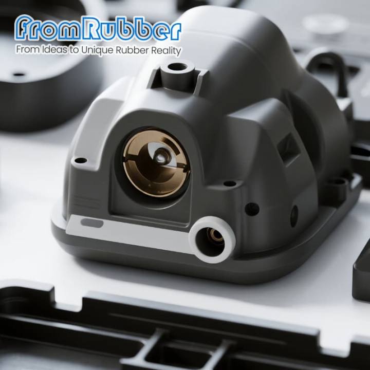
How a custom enclosure programme is quoted and run
The quotation lines follow the decisions above; asking for them separately is what makes two quotes comparable.
Inputs
3D model, 2D drawing with critical dimensions, annual volume, material and colour, IP target and the environment.
DFM before steel
Draft, wall sections, gate position, cooling layout and ejection points reviewed with the customer, in writing.
First article
Dimensional report, material certificate, colour reading and a functional check on the assembled product.
Volume and amortisation
Cavity count, cycle estimate, tool amortisation period and packaging, each shown as a separate line.
Cavity count and how an enclosure quotation scales
Cavitation is a volume decision dressed as a technical one. A single-cavity tool costs least to build and most per part; a four-cavity tool costs roughly two to three times as much and halves the machine time per part. The break-even sits where the saved cycle cost repays the extra tool within the programme life, and it is usually reached earlier than buyers expect on a part with a long cooling time.
Two caveats keep it honest. First, a multi-cavity tool needs balanced runners, or the cavities fill at different rates and the parts differ in weight and warp. Second, quality risk grows with cavity count: a defect in one cavity can run for hours before it is noticed unless the inspection plan samples by cavity position rather than by box.

Questions buyers ask about enclosure moulding
How long does a new enclosure tool take?
Typically six to ten weeks from approved DFM to first article, depending on cavity count and texture. A prototype or bridge tool can shorten the first samples to two or three weeks.
Can we change material after the tool is approved?
Often yes, with a trial. Shrinkage differs between grades, so dimensions that were tuned for ABS may drift with PC/ABS; recertify the critical ones.
What causes sink marks on a visible face?
Thick bosses and ribs on the opposite side. A boss wall at 60 percent of the main wall, with a radius at the base, removes most of them without touching the outer surface.
Is a texture applied to the tool?
Yes, by laser or chemical etching, and it adds draft requirement. A coarse texture needs more draft than a fine one, which is why texture is agreed before the cavity is cut.
Send the model and the volume, get a DFM note back
FromRubber moulds plastic enclosures and silicone components in Dongguan, and returns written DFM comments with the quotation rather than after the tool is cut. Send the 3D model, the critical dimensions and the annual volume; the reply will name the wall sections, gates and tolerances that decide your part price.
Request a DFM and tooling reviewRelated reading: choosing between ABS and other enclosure materials and custom IP65 plastic enclosures.