Custom Silicone Seals for Irregular Surfaces: How to Handle Uneven Contact and Gaps
- Share
- Issue Time
- Nov 3,2026
Summary
A joint can pass a dimensional check and still leak where the mating surface steps, curves or deflects between bolts. This article explains how to measure the real gap, why extra thickness rarely fixes uneven contact, how flat, lip and stepped sections behave differently, and what to confirm before a silicone seal tool is cut.
A gasket can measure correctly on the bench and still leak on the machine. The drawing says 3 mm thick, the incoming inspection says 3.02 mm, and the joint still weeps at one corner after assembly. In most of the sealing failures we are asked to look at, the gasket was not the wrong size. It was the wrong shape for the surface it had to sit on.
Nominal dimensions describe a gasket in isolation. They say nothing about what happens when that gasket is pressed against a casting with a 0.3 mm step, a welded flange that pulls slightly during cooling, or a housing where four bolts sit unevenly around a curved edge. On a surface like that, compression is not a single number. It is a distribution, and a leak starts wherever that distribution drops to zero.
This article is about the design and manufacturing side of custom silicone seals for irregular mating surfaces: how to read the surface, how the cross-section should follow it, and what has to be confirmed before a mold is cut.
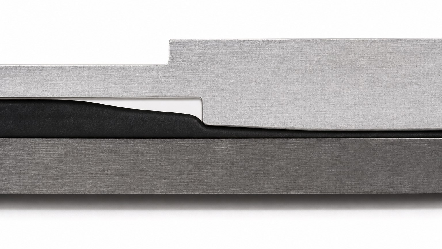
Look at the section below before reading further. Three materials are stacked: an upper machined plate with a step, a black silicone gasket, and a flat lower plate. Follow the gasket from left to right and the thickness of the black band changes. Where the upper plate sits low, the gasket is squeezed thin. Where the plate steps up, the gasket keeps most of its original height and a gap opens above it.
That single picture explains most irregular-surface leaks. The gasket was not too thin or too soft. The metal above it simply was not in the same place all the way around.
What makes an irregular surface hard to seal?
Sealing depends on one condition: the gasket must stay in contact with both mating faces with enough pressure to close the leak path. Everything else — hardness, thickness, profile, bolt torque — exists to maintain that condition. An irregular surface attacks it in three separate ways, and they usually arrive together.
Height steps move the contact line
A step in the mating face changes the distance between the two faces from one point to the next. If the gasket is a flat sheet of constant thickness, the only way it can follow a step is by deforming more in one place than another. Silicone will do that, but only within its compression range. Past that range it stops conforming and starts behaving like a rigid spacer: it holds the joint open where the step is high and leaves a void where the step is low.
The practical consequence is that a leak does not appear along the whole perimeter. It appears at the transition, usually at the outside corner of the step, because that is where contact pressure falls off fastest.
Curvature and draft angle change where the seal touches
On a curved or angled face, a flat gasket does not contact along a line. It contacts along whichever edge happens to sit proud of the surface, and the rest of the section stays unloaded. Machined radii and draft angles make this worse because the effective contact width shrinks as the angle increases. A seal that looks fully seated can be touching on perhaps half of its intended width.
Bolt patterns decide who gets compressed
Bolts concentrate load. Between two bolts, the plates deflect apart. That deflection is small in absolute terms — often a few hundredths of a millimetre on a stiff casting — but it is the same order as the compression reserve in a thin gasket. The result is a pressure map with peaks under each fastener and troughs midway between them. If the trough reaches zero, the joint leaks there regardless of how much torque was applied at the bolts.
This is why simply adding torque rarely helps. More torque raises the peaks, distorts the casting further, and can crush the gasket in the areas that were already sealing.
Why adding thickness rarely fixes an uneven surface
The instinct when a joint leaks is to specify a thicker gasket. Sometimes that works, and it is worth understanding exactly when.
A thicker gasket buys compression travel. If the leak is caused by a gap that is slightly larger than the gasket can accommodate, extra thickness restores contact. But thickness also raises the force needed to compress the joint, and that force has to come from somewhere. On a plastic housing or a thin sheet-metal cover, the extra force deflects the cover instead of compressing the seal, and the gap you were trying to close simply moves somewhere else.
Worse, a thicker gasket in a shallow groove can be over-compressed in the areas where the surfaces are closest. Silicone does not fail gracefully under over-compression: it bulges outward, lifts at the edges, and in extreme cases extrudes into the leak path. The joint then has two problems instead of one — a starved area and an over-compressed area.
The useful way to think about it is a budget. The gap variation across the joint, the flatness tolerance of both faces, the bolt deflection and the gasket's usable compression range all draw on the same allowance. Thickness is one line in that budget, not a fix that sits outside it.
Reading the mating surface before choosing a profile
Before any profile decision, the surface itself has to be measured in a way that is useful for sealing — the step most custom silicone seals projects skip. Nominal CAD geometry is not enough, because the leak is created by deviation from nominal.
What actually matters is the local gap — the distance between the two faces at the point where the gasket will sit — measured around the full perimeter, not just at the corners. A feeler gauge or a thin strip of silicone works for a physical check; a CMM scan of both faces works better if the parts are still in development and the tooling can still change.
Then find the two extremes. The tightest point sets the minimum compression the gasket will see and tells you whether over-compression is a risk. The loosest point sets the maximum gap the gasket must bridge and tells you whether a flat section can reach it at all. Most profile decisions fall out of those two numbers.
Three measurements worth taking before a profile is drawn
- The largest gap between the mating faces along the seal path, measured with the parts clamped as they will be in service.
- The smallest gap, at the tightest bolt or the highest step, to check the gasket will not be crushed beyond its working range.
- The width available for the seal, including any groove walls, so the section can expand sideways without being trapped.
Matching the cross-section to the contact geometry
Once the surface is understood, the profile becomes a design decision rather than a guess. The options below are the ones that come up most often on silicone seals for irregular surfaces, and each one solves a specific problem.
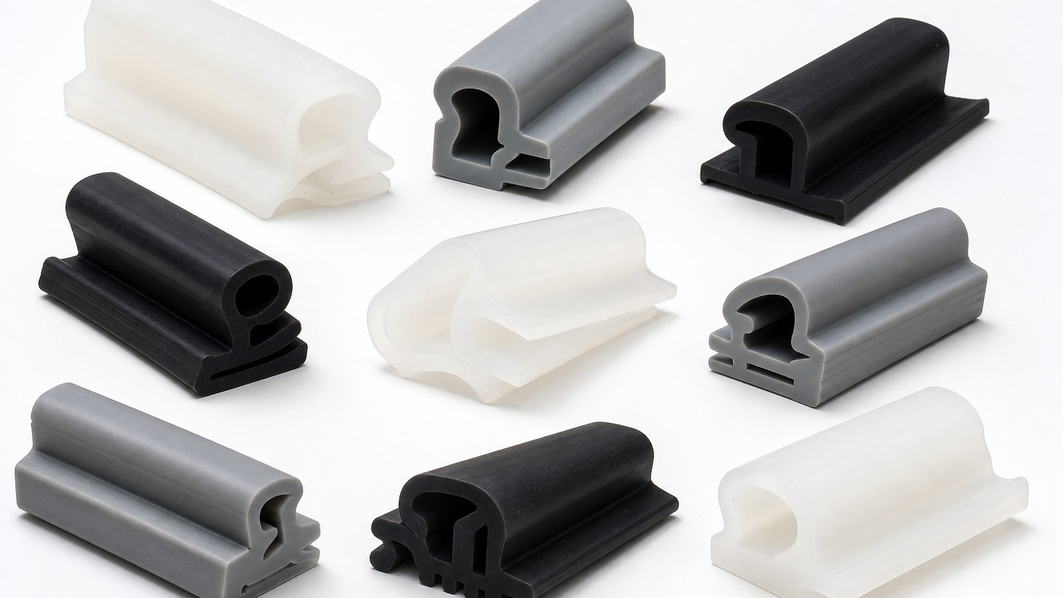
Custom profiles are not about making a seal look complicated. Each change in section does a job: a stepped base sits against a stepped face, a raised lip concentrates pressure where the surface is least predictable, and a hollow section lowers the force needed to close a wide gap.
What matters during design is that every feature has a reason tied to a measurement from the previous step. Features added "for safety" usually create a new interference somewhere else.
Flat sections where the surface is genuinely flat
A flat gasket is the most economical option and the easiest to inspect, but it only works when both faces are flat within the compression allowance. On a machined aluminium housing with a ground face, a flat 1.5–2 mm section at 40–50 Shore A is often all that is needed. On a casting with visible machining marks and a step at the parting line, the same gasket will seal in three places and leak in the fourth.
Raised lip profiles where the contact line moves
A raised lip puts the contact area on a narrow band instead of the full width. Because the loaded area is smaller, the same bolt force produces higher contact pressure, and the lip can follow small height changes without needing the whole section to deform. This is useful on curved faces and on joints where the fastener spacing is wide. The trade-off is that the lip is the first feature to take damage during handling and the first to take a compression set if the joint is over-torqued.
Stepped profiles where the mating face has two levels
When the mating surface genuinely has two heights — a recessed pocket next to a raised land, for example — a stepped gasket follows the geometry instead of fighting it. The step in the rubber is designed to match the step in the metal, so both levels reach their intended compression at the same bolt load. This is the profile that most often removes a persistent corner leak, because it stops asking one continuous section to do two different jobs.
Local features rather than full-perimeter changes
Not every problem needs a new profile. A short rib, a local bump, or a small pad at the point where the gap is widest can restore contact without changing the section everywhere else. This keeps tooling simpler and keeps the rest of the joint behaving predictably. In practice, most of the seals we develop for uneven housings are a standard section with two or three local features, not a completely new shape.
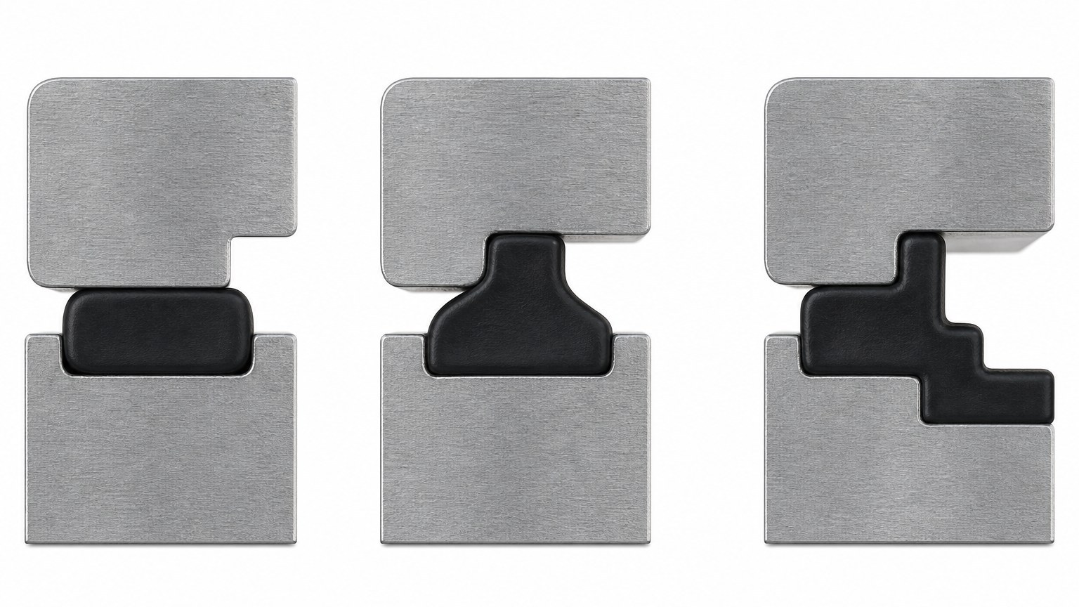
The three sections below sit between the same pair of metal faces. On the left, a flat section contacts across its full width but cannot follow the step. In the middle, a raised lip concentrates load and keeps contact where the face drops away. On the right, a stepped section follows both levels.
Reading the contact geometry this way — rather than comparing compression percentages in a table — is what makes the choice repeatable from one project to the next.
| Section | Where it works | Main risk |
|---|---|---|
| Flat | Face flat within the compression allowance, close bolt spacing | Loses contact at a step or an outside corner |
| Raised lip | Curved faces, wide fastener spacing, limited bolt load | Lip damaged in handling; takes set if over-torqued |
| Stepped | Mating face with two defined levels | Tool cost; the step must follow the metal, not the nominal drawing |
Solid or sponge silicone on an uneven surface?
Material structure changes how a seal behaves on an irregular face, and the choice is often made too quickly in favour of "softer".
Solid silicone is dense and continuous. It holds its section under load, resists extrusion, and gives predictable recovery, which is why it is the default for pressure sealing and for joints where the gasket also has to keep its shape during handling. Its limitation is that conforming to a rough or stepped surface depends almost entirely on having enough compression travel available.
Sponge silicone contains closed cells, so it compresses at much lower force and can absorb a wider gap without loading the housing. That makes it attractive on thin covers and on castings with significant variation. What it does not do is resist pressure: a cellular seal that is comfortable at atmospheric pressure will often pass air or fluid once a differential builds. Our own comparison of the two structures, solid and sponge silicone seals, sets out where each one belongs; the short version is that sponge buys conformity and gives up pressure capability.
There is a third factor that rarely gets discussed: compression set. A sponge seal that spends its life at 60% compression will not spring back to its original thickness when the cover is opened for maintenance, and the second assembly will leak where the first one did not.
What has to be confirmed before a mold is cut
Most of the cost of an irregular-surface seal is decided before the first sample exists. Once the tool is cut, changing the section means cutting again.
The first item is the tolerance the gasket can realistically hold. Compression-moulded silicone parts typically run to ISO 3302-1 classes, with M3 as a commercial default and M2 achievable on smaller parts with well-made tools; a 20 mm dimension at M2 is roughly ±0.25 mm. That number matters because it competes with the surface variation you measured earlier. If the surface varies by 0.4 mm and the gasket varies by 0.25 mm, the compression range has to absorb both.
The second is shrinkage. Silicone moves 1.5–3% during vulcanisation depending on the compound and section, so mold dimensions are built with compensation rather than copied from the drawing. On a long, thin perimeter seal, a small error in shrinkage shows up as a gasket that is right in the middle and short at both ends.
The third is the compression target itself. For a static flange joint, 20–30% compression is the usual working band, and the correct starting hardness for that band is usually 40–60 Shore A. Going softer to chase conformity often backfires: the seal extrudes into the gap instead of resisting it.
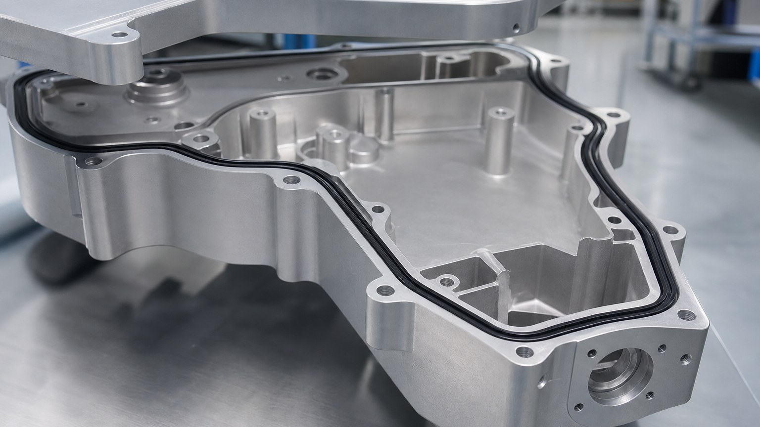
This is the shape of the problem in production. The seal path curves, the surface height changes along it, and the bolt positions are fixed by the housing design rather than by the gasket. A profile that works on the straight section has to keep working around the corner.
When we build a sample for a joint like this, the check is not whether the gasket fits. It is whether the contact marks on the gasket are continuous after the cover has been torqued in the specified sequence.
What to send when you ask for a quote
The fastest way to get a useful answer is to send the information that decides the profile:
- A drawing of both mating parts, not only the gasket, with the tolerances that will actually be held in production.
- The measured gap range around the seal path, or the flatness callout on the mating face if the parts are not yet made.
- The fastening method, bolt count and tightening sequence if it is already defined.
- Working temperature and any media contact, since these narrow the compound choice.
- Whether the joint will be opened for maintenance, which changes how much compression set is acceptable.
- Target annual quantity and whether a prototype tool is acceptable for validation.
With those six items, a profile recommendation and a tolerance check can usually be made without a meeting. Without them, any quote is based on an assumed surface, and the assumption is where the leak starts.
Mistakes that keep coming back
- Designing from nominal dimensions only. A gasket that matches the CAD model can still miss the real surface by more than its compression allowance.
- Treating hardness as a conformity dial. Softer silicone does not follow a step better if the section has nowhere to move; it just extrudes.
- Adding thickness without checking the groove. Extra thickness in a shallow groove converts a gap problem into an over-compression problem.
- Ignoring the tightening sequence. The same gasket and the same torque can seal or leak depending on the order the bolts are run down.
- Approving a sample on its own. A gasket checked flat on a bench tells you nothing about contact pressure in the real joint.
Common questions about sealing an uneven surface
How do you seal a gap on an uneven surface?
Change the section rather than the thickness. Measure the largest gap along the seal path with the parts clamped as they will be in service, then pick a profile that can reach it: a stepped section for a stepped face, a raised lip where the contact line wanders. Extra thickness only helps when the gap is uniform and the joint can still close.
Is a thicker silicone gasket better for an uneven surface?
Only inside the compression budget. Static flange joints commonly sit at 20–30% compression, and a thicker gasket consumes more of the available gap while raising the force the cover has to carry. Past that point the cover deflects and contact pressure becomes uneven.
Can a flat gasket seal a machined casting?
Sometimes, if the face is flat within the compression allowance and the bolts are closely spaced. A casting with a step at the parting line or visible machining marks usually needs a profile change, because a flat section cannot follow the step without losing contact somewhere else.
Related reading from our technical library
- Waterproof silicone seals: design principles, material selection and testing standards
- Silicone seals and gaskets: types, standards and applications
- How to choose the hardness of silicone keys, seals and plugs
- What tolerances compression moulded silicone parts can achieve
- Custom engineered silicone seals
Where this leaves the design
An irregular surface is not a reason to specify a softer or thicker gasket. It is a reason to measure the gap, find the tightest and loosest points, and choose a section that reaches both. Profile, hardness and thickness only work as a set, and the set is defined by the surface rather than by the catalogue.
FromRubber moulds custom silicone seals and gaskets at our Dongguan plant, where 32 compression presses run alongside an in-house tool shop, so section changes can be tried on a prototype tool before production tooling is cut. If you are working on a joint that keeps leaking at one corner, send the mating part drawings and the measured gap range through our inquiry page and we will tell you which profile we would try first — and which ones we would not.
For direct technical questions, the engineers can be reached at nani@fromrubber.com or karl@fromrubber.com, or on WhatsApp and WeChat at +86 18676210913.