Digital Inclinometer Silicone Keypad Sealing Challenges for Dust and Moisture Protection
- Share
- publisher
- FromRubber
- Issue Time
- Sep 16,2026
Summary
A silicone keypad is one part of an enclosure protection system, not a seal on its own. This article looks at where dust and moisture actually enter around a digital inclinometer keypad, how keypad geometry and compression interact with housing design, and what prototype testing can and cannot demonstrate.
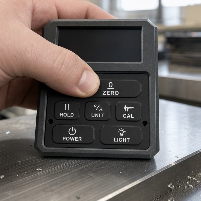
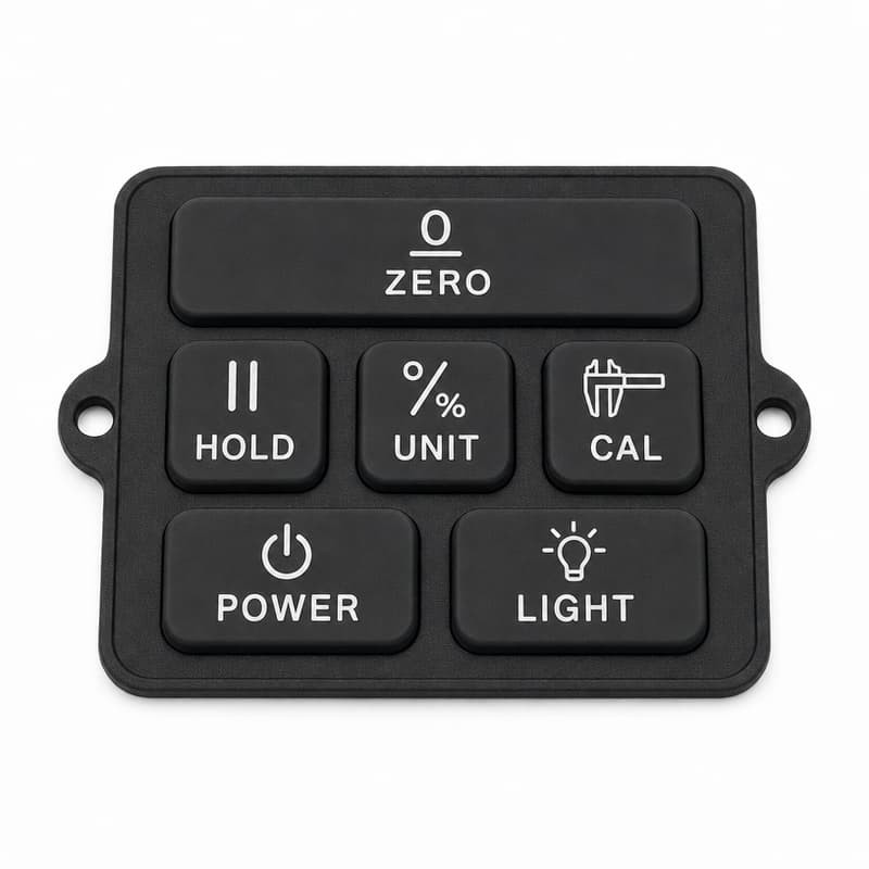
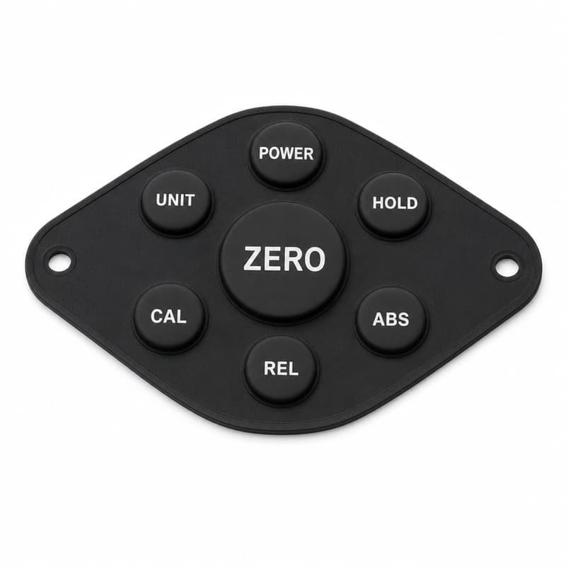
Water rarely gets into a digital inclinometer through the sensor window or the battery door. It gets in around the buttons, and it gets in slowly enough that the first sign is a fogged display rather than a failed instrument. By the time the fault is reported, the unit has usually passed its enclosure test and been in service for months. A digital inclinometer working on a construction site or in a plant is exposed to conditions that an office instrument never sees. The front face of the housing — where the buttons are — is the largest interrupted surface on the product, and every button opening is a potential route inwards. The exposures that matter in practice are unglamorous: The buttons and the enclosure openings are the practical entry points to design against. That is why a digital inclinometer silicone keypad is a sealing component as well as an input device, and why treating it as a decorative cover plate leads to trouble later. A silicone keypad does not, by itself, make an instrument dust-tight or water-tight. It contributes the face seal and the button seals. The protection rating of the finished product is a property of the complete enclosure, tested as a complete enclosure. The perimeter of the keypad is where most leaks begin, and gaps are usually created by dimensions rather than by assembly carelessness. A perimeter that is compressed everywhere except one corner behaves like an open channel. Water travels along the uncompressed edge, and the leak appears far from the actual defect, which is why these faults are so often misdiagnosed as a display window problem. Uneven compression is the most common hidden sealing fault, because the instrument still assembles normally and the buttons still work. Four causes account for most cases: Uneven compression damages two things at once. It opens a route for dust and moisture, and it changes the button feel, so the operator experiences a keypad that is stiff at one end and vague at the other. Tightening the screws further does not solve it; it simply moves the deformation elsewhere. The design of the button openings in the housing determines how much of the keypad is directly exposed, and how much of each button stroke acts like a small piston pushing air and particles into the enclosure. Geometry is where a keypad contributes most to enclosure protection, because the useful features can be moulded in the same operation as the buttons at essentially no added cost. The keypad below is a useful example of layout-driven geometry. The ZERO key is a wide bar across the top, the secondary functions sit in a middle row, and the least-used keys are grouped at the bottom. This is not only an ergonomic choice: the wide bar distributes load across a larger housing opening, and the surrounding border carries the perimeter sealing features without interruption. A moulded rib around the keypad perimeter concentrates compression into a narrow band, which raises the contact pressure between the silicone and the housing at the same closing force. The purpose is not to make the rib large but to make it continuous and to keep it in contact around the full outline, including corners and any cut-outs for locating features. Raised buttons move the working surface away from the housing face, so standing water and dust sit around the button base rather than on top of the opening. This changes how the front face behaves in service, and it is one reason a raised button pattern is often chosen for outdoor instruments. Raised buttons do not make an instrument water-tight. They reduce direct exposure around the openings; the actual barrier is the sealing geometry under them. Controlled compression means deciding where the panel is squeezed and where it stays free. Production keypads commonly separate those two functions: a compression band around the perimeter and around each button base, and a free zone in the web so buttons can still move independently. Retaining features — moulded tabs, locating holes, or a stepped edge — keep the panel in position so the compression band does not migrate during assembly. The material has to keep the sealing geometry working, which is a different requirement from simply being soft enough to press. Compression set deserves particular attention in a sealing context, because a keypad that has taken a permanent set has already lost part of its sealing pressure before the first leak appears. Standardised methods such as ASTM D395 and ISO 815-1:2019 are used to compare materials on that basis, and hardness is verified under a method such as ASTM D2240. What material properties cannot do is substitute for enclosure testing. No compound specification, and no claimed protection level for a keypad alone, replaces a test carried out on the complete instrument. Protection classifications for enclosures are defined in IEC 60529, and the related vehicle-industry interpretation of those classifications is set out in ISO 20653:2023. Both describe the protection of an enclosure, not of a component inside it. Keypad sealing is a system-level design question. The silicone can only close the gap the housing provides, and it can only do so where the housing applies load. The keypad below shows why the envelope matters as much as the button pattern. Its outline is not rectangular — the shape narrows towards the ends and two locating holes sit outside the button field. Whatever seals this panel has to follow that outline, so the housing must present a matching compression path around a curved and asymmetric perimeter rather than around four straight edges. The practical implication is direct: a well-designed silicone keypad cannot compensate for an enclosure that flexes away from it. Where the housing is thin across the keypad area, adding internal support is more effective than increasing the sealing rib height, because the rib can only seal where it is in contact. The interaction between keypad geometry and enclosure structure is examined in more detail in our guide to silicone keypad and plastic enclosure waterproof sealing design. Even a correct design can be assembled badly, and assembly faults are the ones most easily fixed on the production line. This is where positioning features pay for themselves a second time. A keypad with clear locating geometry either seats or refuses to seat, which makes a folded edge visible instead of invisible. When the panel can be placed in several orientations without complaint, the assembly instruction becomes the only defence, and instructions are the least reliable part of a production process. Perimeter fit and retaining design are treated in depth in silicone keypad and plastic enclosure fit clearance. Sealing validation has three stages, and skipping the first one makes the other two unreliable. Before any environmental testing, inspect the assembled unit for the faults that will cause a leak later: Depending on the product requirement, the tests worth considering are dust exposure, humidity exposure, splash testing and temperature cycling. Temperature cycling is the one most often omitted, and it is the one that reproduces the condensation mechanism described earlier. Actual protection testing has to be performed on the complete instrument enclosure. A keypad tested on its own can demonstrate that the sealing geometry survives compression and temperature, but it cannot demonstrate a protection rating for a product, because the rating belongs to the assembly. That distinction is worth keeping in mind when reading test reports, and we described how laboratory results can diverge from field results in our note on IP67 test reports that pass in the laboratory and leak on site. After exposure, the instrument should be retested rather than only inspected. The four checks that matter are button response, tactile feedback, electrical contact reliability and visible silicone deformation. A panel that passed before exposure and feels different afterwards has told you something about the design even if it still switches. Sealing-related customisation depends more on drawings than on description, because the geometry that seals is internal and cannot be inferred from a photograph. The information that makes a difference is: Cross-sectional drawings are especially valuable here because sealing is a vertical problem. A plan view cannot show whether the sealing rib contacts the housing wall, whether the compression band is fully seated, or how much of the button stroke happens below the opening. Without a section, sealing recommendations become assumptions. Dust and moisture protection for a digital inclinometer silicone keypad depends on coordinated design between silicone geometry, enclosure structure, compression, assembly procedure and environmental testing. No single item on that list carries the result, and improving one while neglecting another usually moves the leak rather than closing it. It follows that custom keypad development for an instrument of this kind is an engineering collaboration rather than a component purchase. The drawings that matter — housing sections, retaining geometry, PCB layout — belong to the instrument manufacturer, and the sealing geometry belongs to the keypad mould. Progress is fastest when both are on the table at the same time. If you have enclosure drawings and a protection requirement for your instrument, send them over. FromRubber manufactures custom silicone keypads and buttons to customer drawings, and the sealing features we can mould are defined by the housing they have to work against. FromRubber is the trading name of Dongguan Bohao Electronic Technology Co., Ltd., a custom silicone keypad manufacturer producing compression-moulded and LSR silicone keypads, buttons and seals to customer drawings. Protection ratings apply to tested enclosures; we describe sealing geometry and material behaviour on the keypad side of the interface only.Why Sealing Matters in Digital Inclinometer Silicone Keypad Design
One clarification worth making early
Common Sealing Challenges with Digital Inclinometer Silicone Keypads
Gaps Between the Keypad and Plastic Housing
Uneven Compression Around the Keypad
Button Openings and External Interfaces
Silicone Keypad Geometry for Improved Enclosure Protection
Perimeter Sealing Ribs
Raised Button Structures
Compression Zones and Retaining Features
Material Considerations for Digital Inclinometer Silicone Keypads
How Housing Design Affects Silicone Keypad Sealing Performance
Dust and Moisture Protection Considerations During Assembly
Prototype Testing for Digital Inclinometer Silicone Keypad Sealing
Physical Fit Inspection
Environmental Simulation
Button Function Verification After Environmental Testing
Technical Information Required for Custom Keypad Sealing Design
Practical Checklist for Digital Inclinometer Silicone Keypad Protection Design
Conclusion
References and Standards Cited
Related reading