How Does Cable Diameter Affect a Rubber Grommet Inner Hole?
- Share
- Issue Time
- Sep 22,2026
Summary
Matching a grommet bore to a catalogue cable size is the most common shortcut in cable pass-through design. This article covers what too small and too large a bore each do, why cable tolerance and jacketing change the calculation, how wall thickness constrains the bore, and how dynamic cables need different geometry from static ones.
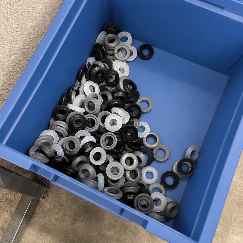
The drawing says 6.0 mm cable, so the grommet bore is drawn at 6.0 mm. Then the real cable arrives at 6.4 mm with its jacket, the fitter forces it through, and the batch is stuck on the bench. Bore sizing is the one grommet dimension where copying the cable's catalogue number is almost guaranteed to be wrong.
Short answer
A grommet bore is not a drilled hole copied from the cable size. It is a controlled clearance that has to absorb the cable's real outside diameter, its tolerance, any jacket or sleeve thickness, and the amount the cable moves. Size it from the assembled cable, not from the wire specification.
Why Cable Diameter and Bore Diameter Cannot Simply Match
The relationship looks obvious and is not. Four things sit between the wire specification and the number that goes on the grommet drawing.
- Jacket thickness. A nominal 6 mm cable is 6 mm over the insulation, and that figure is itself a nominal with a tolerance on it.
- Bundle effects. Where two or more cables pass together, the effective diameter depends on how tightly they are bundled and whether they are taped or sleeved.
- Elastomer deformation. A grommet bore is not rigid. An undersized bore does not refuse the cable; it deforms around it and loads the part in service.
- Movement. A static cable and a vibrating one need different amounts of grip from the same bore.
So the bore is a clearance decision. Too little clearance and the part is stressed at installation; too much and the grommet stops doing its job. The useful range between those two is narrower than most drawings allow for.
When the Bore Is Too Small
An undersized bore does not fail at installation, which is what makes it dangerous. It fits, because silicone stretches — and then it keeps stretching for the rest of its service life.
- Difficult cable insertion. Feeding the cable needs force and often a lubricant, which slows assembly and introduces a handling risk.
- Excessive compression. The wall is permanently strained outward, so the bore no longer sits where the drawing put it.
- Increased stress around the inner edge. The highest strain sits at the bore lip, exactly where a tear or a fatigue crack will start.
- Cable deformation. A tight bore squeezes the insulation, and on a thin-wall cable that squeeze can alter the electrical characteristics or embrittle the jacket over time.
- Load transfer. Because the grommet is gripping hard, every pull on the cable is transmitted into the panel fit.
The compound's elongation at break is the limiting number here, not its hardness. ISO 37 covers how tensile properties including elongation at break are determined, and it is worth having that figure on the material data sheet before deciding how much interference a bore can take.
When the Bore Is Too Large
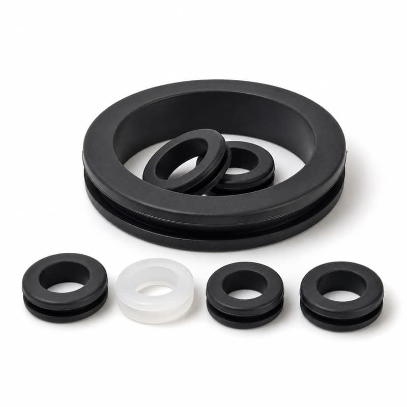
An oversized bore passes every incoming inspection and fails in the field. The grommet is present, correctly fitted, and no longer doing the job it was specified for.
- Excessive clearance. The cable is not held, so it takes the path of least resistance — usually into the panel edge.
- Reduced retention. With nothing gripping the cable, side loads go straight into the groove and the panel fit.
- Increased cable movement. Every vibration cycle becomes a small impact against the bore wall instead of being damped.
- Inconsistent sealing. Where the bore is meant to seal, an oversized fit means the seal depends on the cable happening to sit centrally — which it will not.
- Cable-to-panel contact. If the grommet shifts, the cable can reach the metal edge the grommet was installed to cover.
The failure signature is a worn or chafed jacket with an intact grommet, and it is regularly misdiagnosed as a material problem. Nothing is wrong with the elastomer. The bore is simply not in contact.
From the moulding floor
Bore size is the dimension most often changed after the first samples, almost always because the cable was measured on a bare conductor bundle rather than on the finished assembly.
We ask customers to measure at the point where the cable actually passes the panel, on a finished unit, with tape, sleeve and any strain relief in place. That single measurement usually removes the need for a second sample round — and it is the cheapest measurement in the whole project.
Cable Diameter Variation Is the Real Design Problem
A cable is never a single diameter. It is a range, and the grommet has to work across the whole of it. Four sources contribute:
- Manufacturing tolerance on the jacket itself, which on flexible cables is wider than most drawings assume.
- Nominal versus measured. The catalogue figure is a target, not a guarantee, and different production lots drift.
- Jackets and sleeves. Heat-shrink, braided sleeve, spiral wrap and convolute tubing all add to the effective diameter, sometimes unevenly along the length.
- Local conditions. A bundle that is taped at the pass-through is larger there than a few centimetres away where the tape ends.
The practical consequence: design around the assembled cable's maximum diameter for insertion, and check that the minimum still leaves enough grip. A grommet sized only to the nominal figure will fail at one end or the other — and which end fails depends on the vehicle, which is why the same part can appear to work in validation and fail in service.
Does Material Change the Bore Size You Need?
Yes, and it is one of the most common errors in a material substitution. The same nominal bore in two different compounds does not give the same grip.
A softer compound deforms around the cable, so it tolerates a wider diameter spread before the fit becomes a problem. That tolerance is not free: the same softness means the bore can open under side load, and a soft part takes compression set more readily in a permanently strained position.
A firmer compound holds a bore dimensionally but needs more insertion clearance, and it conforms less well to an irregular cable surface — a sleeved bundle in particular, where the surface is not round.
The interaction runs both ways with wall thickness. Where the wall is thin, the compound's stiffness has less influence because there is less material to resist deflection. Where the wall is thick, the same compound will feel considerably firmer in the bore. Neither property can be specified without the other.
How Wall Thickness Constrains the Bore
Bore diameter, outer diameter and wall thickness are three views of the same geometry. Change one and the other two move, whether or not the drawing acknowledges it.
| Change | Effect on the bore in service | Watch for |
|---|---|---|
| Open the bore, keep the outer diameter | Thinner wall, so the bore deflects further under the same side load | Loss of grip; the cable can now reach the panel edge |
| Open the bore and increase the outer diameter | Wall preserved, but the panel fit changes and installation force rises | Groove and opening may no longer work |
| Reduce the bore, keep the outer diameter | Thicker wall, firmer grip, higher strain at the bore edge | Tear initiation at the inner lip during cable insertion |
| Increase overall height | Longer bearing surface on the cable | Assembly clearance around the opening |
The trap in the last column is that the panel fit and the cable fit are coupled through the same wall. A change made to solve a cable problem can quietly break the groove geometry that was already working. That is why bore revisions should be checked against the panel dimensions every time, not just against the cable.
What Cable Movement Adds to the Calculation
A static cable is a bore-size calculation. A moving cable is a fatigue calculation, and the bore has to serve both.
Static, fully supported. The bore only has to hold the cable and close the opening. Mid-range grip is enough.
Vibration, low amplitude. The bore has to stay in contact through every cycle. A slightly tighter fit is better than a slightly looser one, because contact is what damps the movement.
Repeated bending near the panel. The bore edge becomes a fulcrum. A generous radius and a longer bearing surface matter more than a half-millimetre of bore change.
Lateral pull or drag. The bore has to resist opening. That is a function of wall thickness and compound stiffness together, and it is the case where a soft, thin wall fails first.
Where a single grommet has to cover a genuinely dynamic cable, it is worth accepting a slightly tighter bore than a static application would use — provided the material's elongation and tear strength support it.
Checking the Bore Before Production
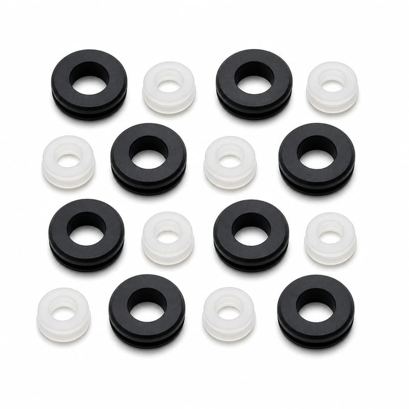
This sequence takes a few minutes and prevents most bore-related returns.
- Measure the actual cable diameter at the pass-through point, on a finished assembly.
- Confirm the cable diameter tolerance range, not just the nominal figure.
- Identify how the cable moves: static, vibrating, bending, or pulled sideways.
- Decide the required retention: does the grommet hold the cable, or simply cover the edge?
- Check the grommet wall thickness after any bore change.
- Re-confirm the panel-side dimensions, since the wall is shared.
- Test insertion by hand and then test the movement the cable will actually see.
Step seven is the one that gets skipped. A bore that passes a hand-insertion check has proved nothing about how it behaves after a thousand vibration cycles.
Can One Bore Cover Several Cable Diameters?
Sometimes, with limits. A flexible grommet can accommodate a range where the cable diameters are close, the walls are thick enough to deflect without over-straining, and the duty is static or lightly loaded. The workable spread on a single bore is modest — often no more than a fraction of a millimetre either side of nominal before grip or strain becomes a problem.
Beyond that, a range-covers-everything approach starts to cost more than it saves. Above roughly a ten per cent spread in cable diameter, separate bores or a differently proportioned profile usually holds better, and the cost of an extra mould is recovered quickly against field failures and rework.
Where the cable varies along its length — a bundle that is taped at the firewall and loose elsewhere — the fit has to be judged at the pass-through point only, at its largest local diameter.
Common bore-sizing mistakes
- Setting the bore to the nominal cable diameter without allowing for jacket deformation.
- Ignoring the cable's own tolerance range.
- Measuring bare conductors instead of the finished assembly.
- Sizing for a static cable when the installation vibrates.
- Changing the bore without reviewing wall thickness and the panel fit.
- Assuming a softer compound will absorb a bore error without any penalty in service.
What to Take From This
The bore is a clearance decision that has to survive a cable's real diameter range, not its catalogue number. Too small and the part is strained from the moment it is assembled; too large and the grommet stops protecting the cable without ever looking wrong.
Measure the assembled cable, work to its tolerance range rather than its nominal figure, and re-check the panel-side geometry every time the bore moves. Those three habits remove most bore-related failure modes before a tool is ever cut.
Sources
- ISO 37:2024, Rubber, vulcanized or thermoplastic — Determination of tensile stress-strain properties. https://www.iso.org/standard/86892.html
- ISO 815-1:2019, Rubber, vulcanized or thermoplastic — Determination of compression set — Part 1: At ambient or elevated temperatures. https://www.iso.org/standard/74943.html
- ISO 48-4:2018, Rubber, vulcanized or thermoplastic — Determination of hardness — Part 4: Indentation hardness by durometer method (Shore hardness). https://www.iso.org/standard/74969.html
- ASTM D2000-18(2024)e1, Standard Classification System for Rubber Products in Automotive Applications. https://store.astm.org/d2000-18r24e01.html