How to Design Rubber Keypad for Medical Diagnostic Devices with Consistent Pressing Feedback?
- Share
- Issue Time
- Nov 12,2026
Summary
Pressing feedback on a diagnostic keypad is a stack-up result, not a material property. This guide covers silicone hardness, wall section, dome geometry, carbon pill alignment and the assembly checks that keep every key on the panel feeling the same.
A diagnostic analyzer comes back from a hospital service team with one complaint: the Enter key feels dead. The membrane is intact, the contact resistance measures fine on the bench, and the keypad passes the incoming inspection exactly as it did when it left the line. Nothing is broken, and the operator still refuses to use it. That gap between "passes the test" and "feels right" is where most keypad design work actually lives.
A rubber keypad for medical devices is judged on feedback long before it is judged on electrical function. Press feedback is not a property of a single button. It is the sum of the silicone, the dome, the skirt, the housing opening, and the pressure the assembly applies to the whole part. Change any one of them and the operator notices. This article walks through where that consistency is lost on medical diagnostic equipment and what to specify so it does not happen.
Why Consistent Pressing Feedback Matters in Medical Diagnostic Devices

An operator running a batch of samples does not look at the panel. They look at the screen, at the rack, at the printout, and their thumb finds the same three keys in the same order several hundred times a shift. That is only possible when every key on the panel gives the same answer to the same question: how far do I move, and how much resistance do I meet on the way down.
Once one key answers differently, the operator compensates. They press harder, or they press twice, or they slow down to watch the screen confirm the input. None of that appears in a functional test report, and all of it shows up in throughput and in the service calls that follow.
How inconsistent button response affects daily equipment operation
The first effect is a silent change in how the instrument is used. A technician who is not sure a key registered will press it again. On a menu-driven analyzer, a double input can move two steps instead of one, and the correction costs more time than the original entry. Nobody logs this as a keypad fault, because the instrument is doing what it was told.
The second effect appears in training and shift handover. New operators learn the panel by feel before they learn the menus. If two units of the same model feel different from each other, the habit built on one machine does not transfer to the next, and the difference gets blamed on the unit rather than on the parts inside it.
It helps to separate the two things that get merged in complaints. A key that feels different but still switches is a tactile feedback problem, and it is a mechanical issue: material, wall section, dome, clearance. A key that feels normal but does not switch is a contact problem: pill position, contact area, contamination, or travel that never reaches closure. The fixes are unrelated, and a complaint written as "the key does not work" usually contains one of the two and sometimes both.
Which medical diagnostic devices require reliable rubber keypad feedback?
Blood analyzers, electrolyte and coagulation instruments, and benchtop immunology units are the obvious cases, because the panel is used continuously during a run and the same keys are hit in the same sequence. Portable diagnostic instruments add a second constraint: the keypad sits inside a hand-held housing that flexes slightly when gripped, so the clearance designed on a drawing is not the clearance in use.
Patient monitoring interfaces and laboratory control panels share the pattern but not the duty cycle. A monitor key may be pressed rarely, yet it must work when someone reaches for it in a hurry, without looking, with a glove on. That is a different requirement from a high-cycle numeric key, and it is worth writing both requirements down separately before the layout is fixed.
Control panels on sample handling and testing equipment sit closest to the mechanical side of the problem. These panels are often large, mounted at an angle, and assembled with several screws that pull the keypad against a PCB. Screw torque distribution, not silicone, decides whether the middle keys feel the same as the corner keys.
What Causes Uneven Pressing Feedback in Custom Rubber Keypads?
In practice, three variables account for most of the inconsistency, and only one of them is the material. The other two are geometry and the assembly preload, and both are usually fixed later in the project than they should be.
| What the operator reports | Usual mechanism | First thing to check |
|---|---|---|
| One key feels soft while its neighbours feel firm | Wall section or dome thickness differs on that key | Wall thickness at four quadrants and dome thickness from the same cavity |
| A key feels stiff at the edge but normal at the centre | Rotation closes the clearance in the housing opening | Clearance at the narrowest section, pressed off-centre |
| A key returns slowly after the press | Compression set, or the skirt rubbing on the opening | Return stroke with the keypad at production torque |
| Every key feels heavier than on the sample | Assembly preload from the board or a boss | Stack height and screw sequence on the assembled unit |
Silicone hardness can change the perceived pressing force
Hardness sets the slope of the force-deflection curve, but the rubber keypad pressing force an operator feels is the whole curve, not the hardness number. A 50 Shore A button and a 70 Shore A button of the same shape do not simply feel softer and harder; they reach their breakover at different travel, and the breakover point is what the finger reads as "click".
The reason hardness alone predicts so little is that the same hardness behaves differently at 6 mm and at 12 mm button diameter, and differently again at 0.8 mm and 2 mm wall. Thick walls raise force faster than hardness does, because force rises with the section that resists compression. A spec sheet that names a hardness but not the section it was measured on says almost nothing about how the key will feel.
The practical consequence for a diagnostic panel is that hardness should be chosen last, after the dome and wall are drawn, or chosen together with them. Choosing hardness first and adjusting geometry afterwards usually lands on a key that meets the force target at the center and feels wrong at the edge.
Different button wall thicknesses create inconsistent deformation
A button is a thin-walled shell, and a shell deforms where it is thinnest. If the skirt is 1.2 mm on one side and 1.8 mm on the other, the thin side buckles first, the button top rotates slightly, and the finger reads that rotation as a soft or vague press even when the total travel is correct.
Uneven sections come from ordinary causes: a draft angle added on one side only, a gate position that leaves one wall fuller, a rib added to stiffen a neighbouring key, a legend recess cut into one wall. None of these look wrong on a drawing. All of them show up as a key that behaves differently from the one next to it.
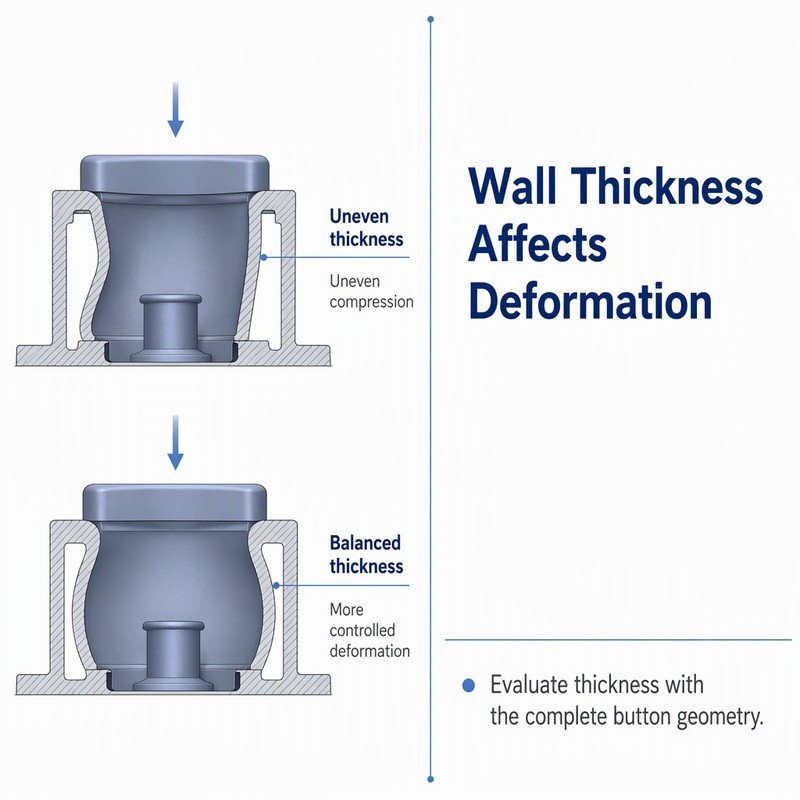
Height matters for the same reason. A taller button has more unsupported sidewall, so a small difference in wall thickness produces a larger difference in lateral movement. Two keys with identical sections but different heights will not feel identical, which is why panels that mix a tall Enter key with flat function keys need the Enter key designed as its own structure rather than as a stretched copy.
Support structures complicate the comparison across a multi-key panel. A common silicone web ties every key together, so pressing one key pulls slightly on its neighbours. On a panel where keys are close together, the web is part of each key's spring, and a web that is uniform in thickness but not uniform in span will make the center keys stiffer than the edge keys. This is one of the few inconsistencies that appears only after molding, because it depends on how the material filled the cavities.
Poor key geometry can affect button travel and rebound
Travel and rebound are set by the gap between the button top and the housing opening, and by the space the dome has to invert. If the dome is too tall for the cavity, it bottoms out before the contact closes. If it is too short, the key reaches the contact pad while the dome is still stiff, and the press feels abrupt rather than progressive.
Clearance is often specified as a single radial number, which hides the real risk. What matters is the clearance at the point of maximum sideways movement, after the button has rotated. A generous gap at rest can still close on one side during an off-center press, and the resulting friction is felt as a key that is stiff at the edge and normal at the center.
Rebound deserves its own check. Silicone returns because it is elastic, but a key that has been compressed against a housing wall returns more slowly, and a key whose dome has taken a compression set returns incompletely. Both read to the operator as a sluggish key, even though the material itself is within specification.
How to Design the Internal Structure for Consistent Tactile Feedback
Silicone keypad tactile feedback design has a short sequence: fix the dome, then the wall, then the contact, then check all three against the housing. Doing them in the other order is what produces a panel that needs a new mold after the first prototype assembly.
Select the right dome geometry for the required pressing response
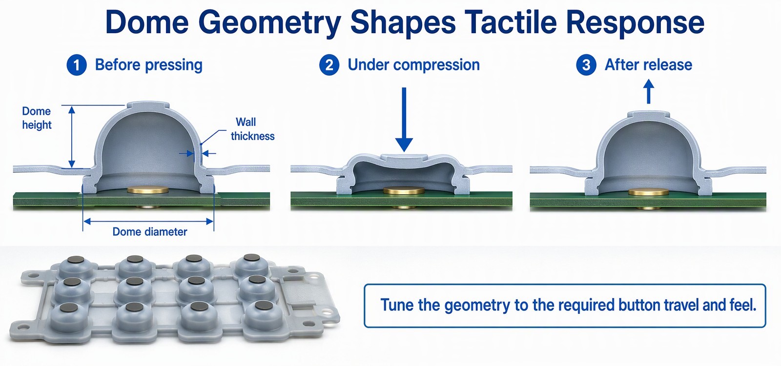
A keypad dome is the molded arch under the button, and it acts as the spring: it stores the press and returns the key.
Most silicone keypads use one of three dome families: a simple conical dome, a dome with a flat top and a sharp transition, and a dome with a controlled shoulder that inverts progressively. The differences are not cosmetic. A conical dome gives a long, soft ramp and a wide breakover; a dome with a sharp transition gives a short, defined click but concentrates stress on the transition line, which is where a tear starts first on thin parts.
Dome diameter and height together set the travel before inversion. For a given height, a larger diameter softens the dome and lengthens the ramp. For a given diameter, a taller dome increases travel but reduces the force available to return the key. That trade is the reason a large Enter key and a small function key on the same panel cannot share one dome profile and still feel alike.
Wall thickness of the dome itself is the least visible variable and the most sensitive. A dome that is 0.1 mm thicker than its neighbour on the same panel will feel noticeably firmer, and the difference is well inside normal molding tolerance unless the cavity is controlled. On medical panels where a service technician may compare one unit against another, that is enough to generate a complaint.
Balance button height and supporting wall thickness
The useful way to think about height is as unsupported span. A button top that sits far above its skirt has a long lever, so any side load produces a visible tilt. Reducing height is the most direct way to stabilise a key, and it is also the change that operators notice least, because travel is set by the dome rather than by the visible cap height.
Wall thickness should follow the load, not the drawing habit. Frequently pressed keys on a diagnostic panel, the numeric block and the confirm key in particular, benefit from a slightly thicker skirt that resists sideways deformation, while keys that are pressed once per run can stay thin so they still register with a light touch. Making every wall on the panel the same thickness is simple to draw and is one of the reasons panels feel inconsistent key by key.
There is a limit in both directions. Walls thick enough to resist deformation also resist the dome's inversion and raise the force needed to close the contact, which is felt as a heavy key rather than a stable one. The target is a button that moves in one direction only, with enough section to prevent rotation and not enough to fight the dome.
Match conductive pill placement with the PCB contact design
A conductive pill is a small carbon-loaded silicone pad molded onto the underside of a key, and it closes the circuit when it meets the PCB contact pad. The carbon pill is therefore a switch element, and its position is a mechanical decision with electrical consequences. The pill must sit under the center of the button travel, not under the center of the button cap. On a key whose top is offset from its dome, those two centers are not the same point, and a pill placed by eye on the cap will close the circuit off-center, with a smaller effective contact area and a shorter life.
Pill diameter should be matched to the PCB pad with some margin for lateral movement during the press, because the button does rotate slightly even when the design is good. A pill that is barely larger than the pad leaves no allowance for that movement; a pill that is much larger than the pad wastes force and can bridge adjacent traces on a tight layout.
The other point worth separating is that mechanical feel and electrical closure are two different acceptance criteria. A key can feel perfect and close late, or close early and feel dead. Both are measured on the same force-displacement curve, but they are read at different points on it, and a supplier who only reports actuation force is reporting one number from a two-number story.
What Should Manufacturers Check During Silicone Keypad Production?
Consistency is a production question, not a design question. A perfect drawing produced from an uncontrolled process gives a panel where the first keys off the tool feel right and the last ones do not.
Control silicone material consistency between production batches
Hardness drift between batches is small but cumulative in effect. Two lots of the same nominal compound can differ enough that keys molded from each feel different when assembled into the same housing, particularly on thin skirts where the section is least able to mask the difference. Incoming checks on hardness, tensile and tear properties catch the obvious cases; the subtle ones show up as a shift in feel across a production run.
Material preparation matters as much as the material. Compound that has been warmed unevenly, or that has picked up moisture in storage, does not flow the same way into a multi-cavity tool, and the cavities that fill last end up with slightly different density and slightly different stiffness. That is how a panel ends up with one key that is firmer than the other eleven, with no visible defect to explain it.
Inspect button dimensions and molding consistency
Dimensional inspection on a keypad should cover button height, dome thickness, skirt thickness at four quadrants, and overall flatness of the base. Height and flatness are the two that most directly translate into feel, and flatness is the one most often skipped. A base that is slightly bowed pulls the whole keypad against the PCB unevenly, and the keys over the high point end up preloaded before the first press.
Flash and incomplete fill deserve a specific look at the parting line, because a thin flash ring around a button changes the clearance that was designed for it. On a handheld or portable diagnostic instrument, a flash ring of a few tenths of a millimetre is enough to convert a free-moving key into a rubbing one after assembly.
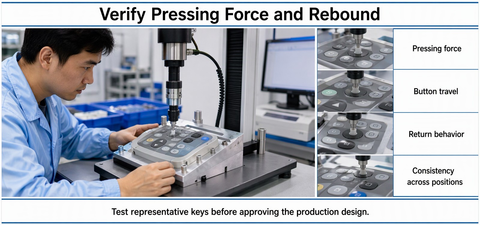
Test pressing force and rebound performance
A force-displacement test gives the shape of the press: the initial ramp, the breakover, the contact closure point, and the return path. Two keys can share the same peak force and still have different curves, which is why reporting only the peak hides exactly the inconsistency the operator complains about.
Sampling should cover the panel rather than one representative key. The four corners, the center, and the largest and smallest keys are the minimum set, because those are the positions where molding fill, web span and housing preload differ most. On a new tool, the same test run on parts from the first, middle and last cavities of a production cycle is more informative than a larger sample from one cavity.
Material data is a useful frame here, as long as it comes from a real datasheet rather than a rule of thumb. FromRubber publishes a summary of a 70 Shore A compound that lists hardness 70 ± 5, tensile strength 5.0 MPa as the requirement with 5.7 MPa achieved, and elongation at break 150 percent required with 266 percent achieved. The elongation figure is the one that matters for a keypad skirt: a material that stretches well before it tears tolerates the repeated bending at the skirt transition, which is where thin sections fail first. Those numbers describe one compound and one test, not a specification for every keypad.
Rebound should be checked with the keypad mounted, not loose on a bench. The housing is part of the spring, and a key that returns cleanly on a bench can hang in the opening once the cover is screwed down.
How to Develop a Custom Rubber Keypad for Medical Diagnostic Equipment
Provide the equipment interface and button layout before mold development
For custom rubber keypads for diagnostic equipment, the useful starting package is small and specific: the housing opening dimensions with tolerances, the PCB contact layout, the button arrangement with intended functions, the surface the keypad seals against, and the assembly method with its screw positions and torque values. A 3D model of the housing helps, but the opening dimensions and the PCB pad positions are what the tool is actually built around.
Two details are worth resolving before any tooling starts. First, whether the keypad is captured by the housing or bonded to it, because a captured keypad needs clearance for the housing to slide over it and a bonded one needs a flat, clean bonding surface. Second, which keys carry legends and by which route, molded, printed or laser etched, because the legend method changes the wall section at the key top and can change the feel of the key.
Confirm material hardness and tactile requirements through samples
Samples are where a buyer can compare feel against the requirement rather than against a number. The productive way to evaluate them is to press the sample panel the way the instrument is used, with a glove if the application uses gloves, and at the edge of the keys as well as the center. A sample that feels right at the center and vague at the edge is a geometry problem that will still be there in production.
It also helps to compare samples from two hardness levels with the same geometry rather than two geometries with the same hardness. That isolates the material variable and gives the buyer a real choice instead of a guess.
Evaluate the complete keypad assembly before mass production
The assembly check is the one that catches the failures the bench test cannot. Fit the keypad into the actual housing with the actual PCB, tighten the screws in the production sequence and to the production torque, then press every key at the center and near the edge. Listen for rubbing, watch for slow return, and confirm that the contacts close at the point in the travel where they were designed to close.
If the instrument has a display, run the panel through its real menu sequence rather than a key-by-key test. Sequences expose the interaction between adjacent keys and the double-input problem that a single-key test never shows.
What to send with a keypad enquiry
A housing drawing with opening dimensions and tolerances, the PCB contact layout, the button layout with functions, the required legend method, the expected production quantity, and the surface finish of the housing around the panel. With those five, a supplier can evaluate clearance and dome geometry before quoting tooling. Without them, every quote is a guess that gets corrected at the sample stage.
Frequently Asked Questions About Medical Device Rubber Keypads
What silicone hardness is suitable for medical diagnostic keypads?
There is no single answer, and a supplier who gives one without asking about button size and wall section is guessing. On a typical diagnostic panel, the hardness is chosen together with the dome and skirt so that all keys land on the same breakover feel. If a starting point is needed, it should come from a sample comparison on the actual geometry, not from a catalogue value.
How can manufacturers make multiple rubber keypad buttons feel consistent?
By controlling the three variables that differ across a panel: wall section at four quadrants, dome thickness, and the web span between keys. Inspection should measure all three per key rather than one key per panel, and the force-displacement curve should be sampled at the corners and center, not only at a representative key.
Can custom silicone keypads be designed with different pressing forces?
Yes, and on mixed panels they usually should be. A confirm key that is pressed deliberately and a numeric key that is pressed in rapid sequence do not need the same force. The practical limit is that the differences come from geometry, so each force level needs its own dome and wall design, which affects tooling cost and the number of cavities.
What information should buyers provide when requesting a medical keypad quotation?
Housing opening dimensions with tolerances, PCB pad layout, button layout and legends, assembly method with screw positions, and production quantity. A 3D file of the housing is helpful but not a substitute for the opening dimensions, because those tolerances are what the clearance is calculated from.
Where this leaves a diagnostic keypad project
Consistent pressing feedback in medical keypads is a stack-up result: material, dome, wall section, clearance and assembly preload, evaluated together and inspected on the panel rather than on one key. The projects that avoid service complaints are the ones where the force-displacement curve was checked at the corners as well as the center, and where the final check happened with the keypad screwed into its housing.
FromRubber (Dongguan Bohao Electronic Technology) molds custom silicone keypads for diagnostic, laboratory and industrial instruments, including conductive carbon pill designs, molded and laser-etched legends, and multi-key panels where each key is drawn as its own structure. Work is carried out under ISO 9001:2015 and IATF 16949:2016 quality systems, and the engineering team reviews housing drawings and PCB layouts before tooling so clearance problems are found on paper rather than at the sample stage.
If you have a panel where one key feels different from the rest, send the housing drawing and the PCB layout for a clearance review: contact the FromRubber engineering team. For drawings and interface questions before tooling, the silicone keypad design and technical support page lists what the team needs to quote. WhatsApp and WeChat: +86 18676210913.
Sources and supporting reading
- Antimicrobial silicone keypads for patient monitors: how additives shift hardness and rebound
- Uneven carbon pill distribution and what the molding process does to contact consistency
- Why some keys on the same silicone panel feel harder than others
- Why a silicone keypad becomes hard to press over time
Have a panel with one key that feels wrong?
Send the housing opening dimensions, the PCB pad layout and the button layout. The engineering review covers clearance, dome geometry and legend method before tooling is quoted.
Request an engineering review