How to Match a Voice Amplifier Silicone Keypad with Its Plastic Housing?
- Share
- publisher
- FromRubber
- Issue Time
- Nov 20,2026
Summary
A voice amplifier silicone keypad can meet its own drawing and still fail in the housing. Fit is a tolerance stack across the keypad profile, the button openings, the frame thickness, the internal depth and the PCB height. The article explains why flexibility does not absorb dimensional error, which interfaces to measure first, how retaining features should be designed, and how to verify the assembly before the mold is opened.
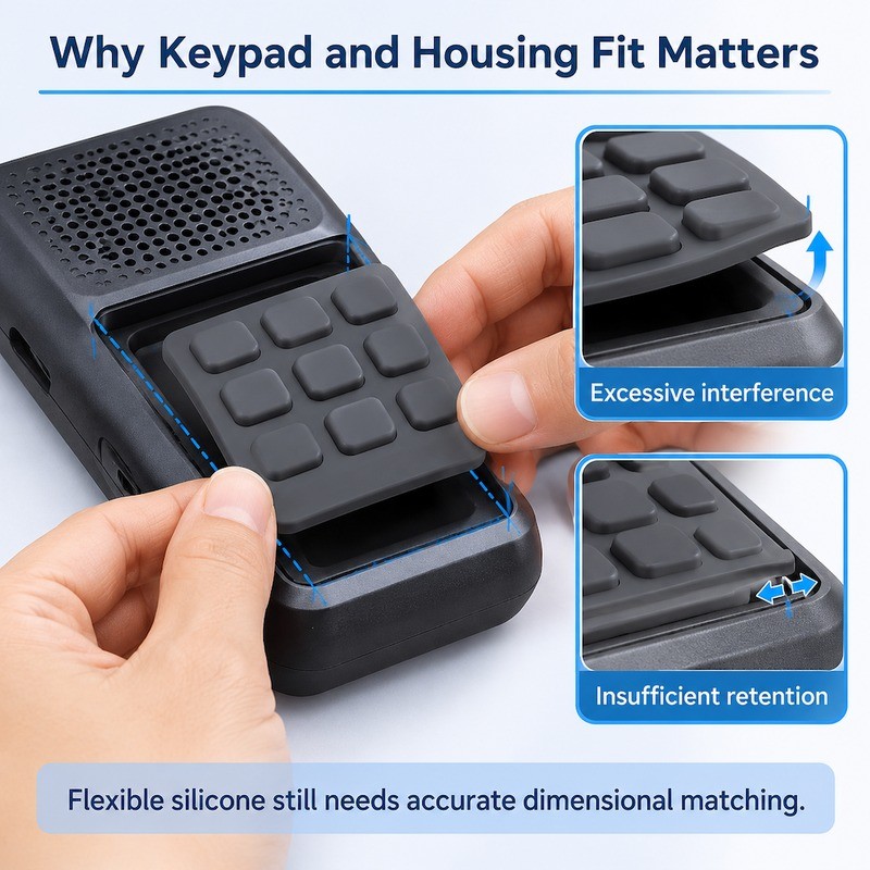
A voice amplifier keypad can be dimensionally correct on both drawings and still fail to assemble. The silicone part measures within tolerance, the plastic housing measures within tolerance, and the keypad lifts at one corner, folds along an edge, or pinches the buttons until they stop returning. The reason is usually that the two drawings were checked separately and never as a stack.
Matching a voice amplifier silicone keypad to a plastic housing is a tolerance-stack problem, not a single dimension. The keypad's outer profile, the housing opening, the depth available behind the panel, the position of the PCB and the retaining features all contribute to the same fit. Silicone is flexible, but flexibility does not absorb a dimensional error; it converts it into lift, fold or compression that shows up later as a button problem.
Why Is It Difficult to Match a Silicone Keypad With a Plastic Housing?
Two materials with different stiffness, different thermal expansion and different molding behavior have to locate each other within a fraction of a millimetre, in a device that will be carried, dropped and left in a vehicle. The difficulty is not the nominal dimension. It is what happens around it.
Silicone rubber moves roughly an order of magnitude more than rigid plastic when temperature changes, and it is far more compliant in compression than in tension. A keypad that fits at room temperature can be tight in a cold store and loose after a day in the sun, not because it changed shape but because the housing did.
The plastic housing also carries its own molding variation: warpage across a large flat face, draft on the inner walls, and sink opposite thick features. A keypad designed against the nominal CAD housing meets a real part that is slightly different in exactly the places that matter for fit.
Silicone and Plastic Components Behave Differently During Assembly
Silicone is nearly incompressible in volume but very compliant in shear and bending. When it is forced into a space that is too small, it does not compress like foam; it bulges somewhere else. In a keypad that bulge appears as a raised edge, a wave across the frame, or a cap that leans against the side of its opening.
Plastic is the opposite. It resists deformation until it either seats or cracks. The assembly therefore has one part that accommodates by moving and one that does not, and the movement always happens in the least constrained direction, which is usually the visible edge.
Small Dimensional Deviations Can Affect the Overall Keypad Fit
The outer profile is the first interface. If the keypad is slightly large, it will not seat without folding; if it is slightly small, it will sit down but leave a gap that collects dust and looks like a defect. Both conditions can occur on the same part if the profile is uneven, which is why the outer dimension should be checked at several points rather than as a single length.
Thickness is the second. The keypad is usually clamped between the housing and an internal support, and that clamp is what holds it in place. A thickness variation of a few hundredths of a millimetre changes how much the frame is compressed, and therefore how much the caps are pre-loaded before the user touches them.
A Keypad That Fits the Drawing May Still Be Difficult to Install
Assembly direction matters. A keypad that is designed to drop in from the front behaves differently from one that is pushed in from behind, and a keypad that has to pass a rib on the way in may need a lead-in chamfer that the drawing does not show. Fitters compensate by stretching or folding, and the deformation stays in the part.
This is why we ask for the assembly sequence, not only the final position. The same part can be easy or impossible to install depending on the order of operations, and the fix is often a small change to a locating feature rather than a change to the keypad outline.
Which Dimensions Matter Most When Matching a Silicone Keypad With Its Housing?
Four interfaces decide most fit outcomes. They should be identified on the drawing and measured on the first sample, before any cosmetic judgement.
The outer profile controls seating and appearance. The button openings control whether the caps can move freely. The thickness controls clamping and pre-load. The internal depth controls how far the caps can travel before they bottom out on the PCB or the housing.
When a fit problem appears, these four are the ones to measure first. Cosmetic symptoms such as a lifted corner or a visible gap are consequences, and adjusting the cosmetic feature rarely fixes the cause.
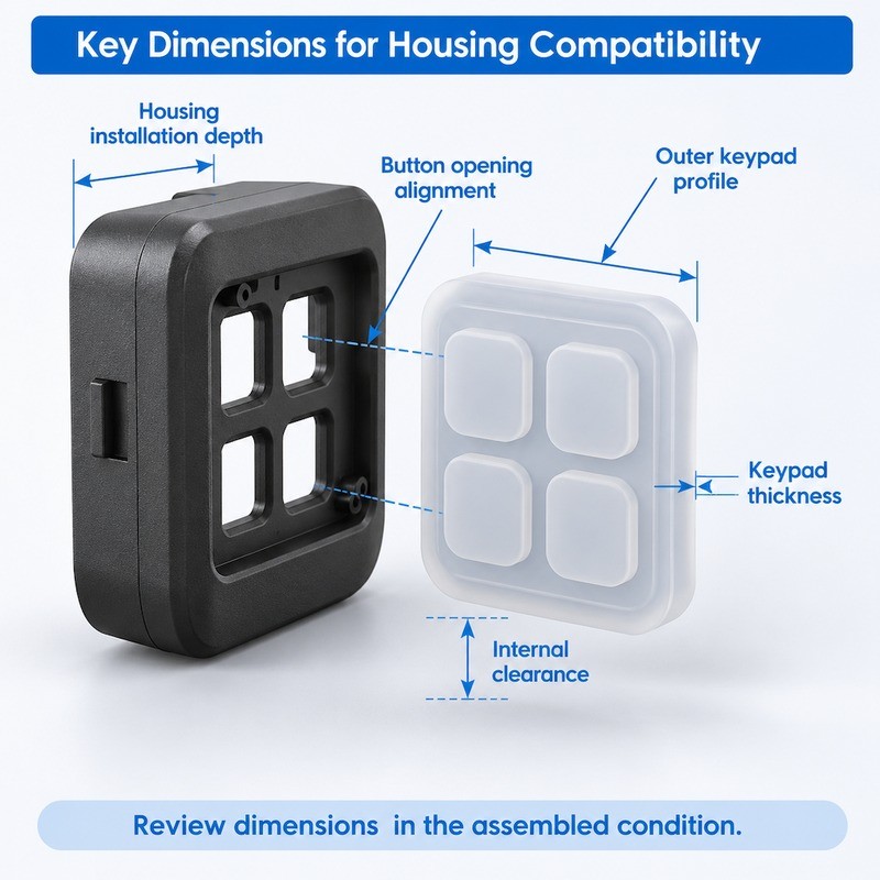
Outer Dimensions Must Match the Housing Installation Area
The keypad's outer length and width have to sit inside the housing's locating pocket with enough clearance to allow for silicone molding variation and plastic warpage, and little enough to prevent movement. That window is narrower than most drawings suggest, because both parts vary in the same direction at the same time more often than statistics imply.
Where the keypad is retained by an outer frame that is clamped, the frame width has to be wide enough to seal and narrow enough to leave cap area. A frame that is too narrow lifts under compression; one that is too wide reduces the space available for caps and webs.
Button Openings Must Align With the Plastic Panel
Each cap needs clearance in its opening, all around, at the worst-case combination of positions. If the cap touches the plastic on one side, the button will feel heavier and will return more slowly, and the side that rubs will eventually show a polished mark that reads as wear.
The opening also acts as a finger guide. Too much clearance and the cap wobbles under an angled press; too little and the cap binds. The usable range depends on cap height and on how far the cap protrudes above the panel.
Keypad Thickness and Housing Depth Affect Button Movement
Thickness is often treated as a single number, but a keypad has several: frame thickness, base thickness under the caps, and cap height. The frame thickness sets the clamp; the base thickness sets how much the wall can deflect before the base itself moves; the cap height sets the stroke.
Depth behind the panel has to accommodate all three plus the PCB. When the internal space is short, the cap bottoms out early and the user feels a hard stop. That is a fit problem that presents as a pressing-force problem, and it is one of the most common misdiagnoses we see.
| Interface | What it controls | Failure if too tight | Failure if too loose |
|---|---|---|---|
| Keypad outer profile to housing pocket | Seating, edge appearance, lateral location | Folding, edge lift, distortion of the frame | Movement, dust gap, misalignment with openings |
| Cap to opening clearance | Free movement and return | Rubbing, slow return, polished wear marks | Wobble, angled press, cap can catch on an edge |
| Frame thickness at the clamp | Retention and pre-load on the caps | Over-compression, caps held down, poor return | Keypad not held, lifts when operated |
| Depth behind the caps | Available travel before bottoming out | Hard stop, high force at end of stroke | Excess travel, mushy feel, poor contact force |
| Locating feature to housing rib or groove | Position repeatability during assembly | Feature will not enter, keypad distorted to fit | Keypad shifts, caps no longer centred on pads |
| PCB height to base of keypad | Contact closure point | Pre-loaded contacts, cap sits high | Contact never closes, or closes only at full stroke |
How Do Retaining Structures Affect Silicone Keypad Installation?
Retention is the part of the design that is easiest to overdo. The instinct is to hold the keypad firmly, and firm retention in a flexible part means compression, which means pre-load on the buttons.
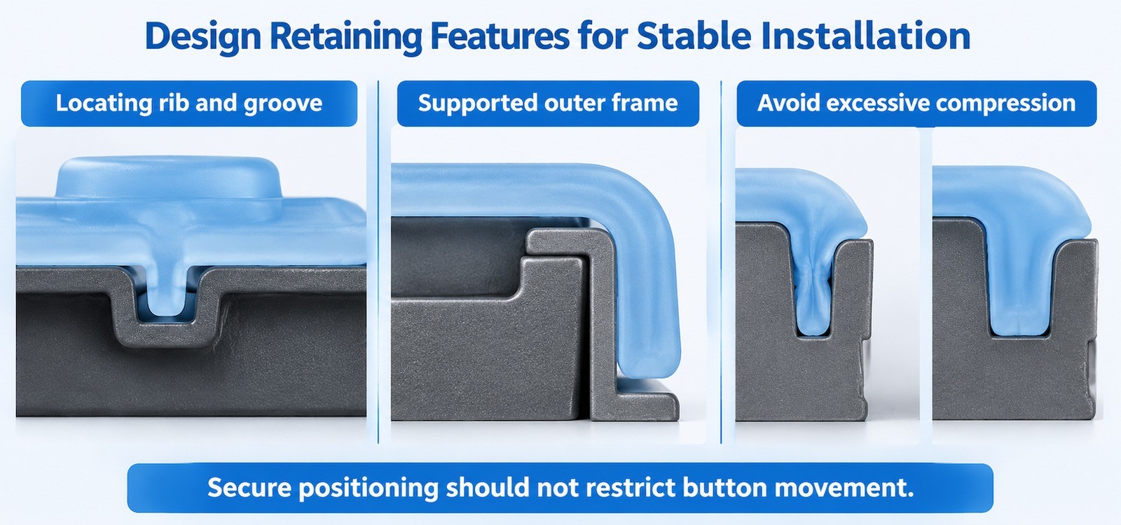
Positioning Ribs and Grooves Help Control Keypad Movement
A small rib on the keypad edge that enters a groove in the housing fixes the keypad in one direction without compressing the frame. It is a location feature, not a clamp, and it should be designed with clearance so that it enters easily and does not fight the outer profile.
The rib also has to survive demolding. A rib that is too tall or too sharp will tear at the base when the part is stripped, and the tear will be on the visible edge. Rounded ribs with a generous base radius are more robust and work just as well for location.
Outer Frames and Supporting Edges Help Maintain the Keypad Position
A supported outer frame distributes the clamp load over a larger area, which reduces the compression at any one point. This is the more forgiving retention method for a flexible keypad, because the frame can deform slightly without moving the caps.
The support has to be continuous. A frame supported at four points and free between them will bow between the supports, and the caps near the middle of each span will sit lower than the rest. Checking the support surface for flatness is part of the housing inspection, not only the keypad inspection.
Excessive Retention Pressure Can Distort the Silicone Structure
When the retaining structure compresses the frame, the material has to go somewhere. It typically bulges toward the caps, narrowing the clearance around them, or lifts the centre of the keypad away from the PCB. Both effects appear as button problems after a few weeks, when the compression set has developed.
The right question is not "how hard can we clamp" but "how little clamp is enough to keep the keypad located". For most handheld products, location features plus a light clamp are sufficient, and the lighter clamp leaves the button feel intact.
How Can Engineers Prevent Fit Problems Before Opening the Mold?
Fit problems are cheapest to fix on paper and most expensive after the tool is cut. The review below is the sequence we follow before a keypad mold is released.
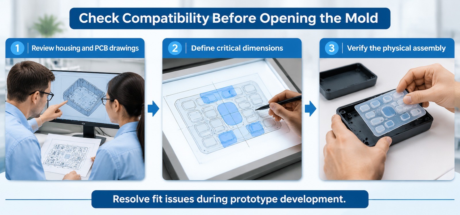
Review the Plastic Housing and PCB Drawings Together
The housing drawing shows the pocket, the openings and the support surface. The PCB drawing shows the pad positions and the component heights that limit how far the keypad can sit down. Together they define the space the keypad actually occupies.
Overlay the two in the same coordinate system and look for conflicts: a tall component under a cap, a support rib that lands on a web instead of the frame, an opening that is offset from a pad. These are easy to see in an overlay and almost invisible when the drawings are reviewed separately.
Define Critical Dimensions and Assembly Tolerances
Not every dimension deserves a tolerance. The ones that matter are the outer profile, the cap positions, the frame thickness at the clamp and the locating features. Those should be dimensioned with a stated method and checked on the first article.
The tolerance has to account for both parts, and the two parts should be specified against a shared reference: the tolerance classes in ISO 3302-1 for the moulded rubber dimensions, and the housing drawing's own tolerance for the plastic. A keypad tolerance that consumes the entire available clearance leaves nothing for housing warpage, and the assembly will fail on the parts at the edge of the distribution even though every part is in tolerance.
Use Physical Samples to Verify the Actual Assembly
Install the keypad into the real housing, with the real PCB, following the real assembly sequence. Check for edge lift, folding, displacement and cap interference, then operate every button and confirm travel and contact.
Do this before approving the production mold, and do it more than once with parts from different cavities if the tool is multi-cavity. A single good sample proves that the design can work; it does not prove that the tool will produce it consistently.
What Should OEM Buyers Provide When Customizing a Voice Amplifier Silicone Keypad?
The information below lets a supplier evaluate fit before quoting, and it prevents the sample round that otherwise gets spent discovering the housing.
Housing drawings
2D drawings or 3D CAD of the front housing, including the pocket, openings and support surfaces.
PCB data
Pad coordinates, pad diameter, switch type and the height of any component that sits under the keypad.
Keypad requirements
Outer dimensions, cap positions, frame width and any locating features already defined.
Installation details
Assembly direction, retention method and whether the keypad is clamped, bonded or held by the housing.
Material and finish
Hardness range, colour, surface texture and legend method, since these affect thickness and friction.
Reference parts
A physical housing sample, a previous keypad or a competitor part is often more useful than a complete drawing set.
How Can a Custom Silicone Keypad Manufacturer Improve Housing Compatibility?
The manufacturer's value in fit work is that keypad geometry, mold design and trimming all sit in one place. A supplier who molds the part can change a frame width or a locating rib in the tool and re-check the assembly, rather than re-quoting the whole project.
At FromRubber, keypad projects are reviewed against the housing drawing before the mold is designed, and the first samples are assembled into customer housings where samples are available. The custom silicone keypad page covers the constructions we mold, the mold making page describes the in-house tool shop, and the injection molding capability matters when the same project needs a plastic housing or a plastic frame.
Sealing is often part of the same fit problem. A keypad that has to keep water out needs a controlled compression at the frame, which is the opposite of the light clamp that preserves button feel. Constructions such as the waterproof and sweatproof keypad resolve that conflict with a dedicated sealing feature rather than by clamping harder. The marine keypad design notes discuss the same trade-off in a more severe environment.
When the Housing Should Change Instead of the Keypad
There are cases where the housing is the wrong part to keep. If the pocket is too shallow for the required travel, or the support surface is not flat, no keypad geometry will produce a consistent feel. In those cases the honest answer is that the housing needs a change, and it is better to say so before the keypad tool is cut.
Our custom product service process includes a drawing review stage for exactly this reason, and the keypad FAQ covers the questions that come up most often at that stage.
Frequently Asked Questions
Why does the keypad lift at one corner after assembly?
Usually because the outer profile is slightly large for the pocket, or the frame is being compressed unevenly. The material relieves the compression by lifting at the least constrained point. Measure the profile at several positions and check the support surface for flatness.
Can a flexible keypad compensate for housing warpage?
Only within a small range. Silicone will conform to a gentle curve, but it does so by changing the position of the caps. Once the caps move far enough to affect contact alignment or opening clearance, the warpage has to be corrected in the housing.
Should the keypad be bonded or mechanically retained?
Mechanical retention is easier to service and avoids adhesive creep, but it needs locating features and a controlled clamp. Bonding suits thin keypads and sealed designs, where the adhesive also acts as the seal. The choice affects the frame width, so it belongs in the early layout work.
How much clearance is needed around each button in the opening?
Enough that the cap cannot touch the plastic at the worst-case position, and little enough that the cap does not wobble. The exact figure depends on cap height, opening depth and how the user presses. It should be verified on the assembled sample, not only calculated.
Does silicone thickness tolerance affect button feel?
Yes. The frame thickness sets the clamp, and the base thickness sets how much the wall can deflect before the base moves. Both should be toleranced, and both should be measured on the first article.
Sources and verification notes
- FromRubber technical article: which details matter in marine silicone keypad design.
- FromRubber technical article: button height and panel assembly.
- FromRubber process page: rubber and plastic mold making.
- Standard designations referenced for orientation only, by name: ISO 3302-1 (dimensional tolerances for rubber products), ISO 48-4 (hardness). Confirm the applicable class and edition with your supplier and test house.
The fit relationships described here come from keypad and housing reviews on handheld audio and instrument products. No nominal dimensions or tolerance values are quoted, because the correct figures depend on the specific housing, the PCB height and the retention method.
If a keypad fits on the drawing but not in the housing, send the housing sample with the keypad and note where it lifts or binds. That combination usually identifies the interface within one review.
FromRubber, Dongguan Bohao Electronic Technology Co., Ltd.
WhatsApp and WeChat: +86 18676210913. The contact page reaches the same engineering team.