How to Prevent Button Sticking in Custom Silicone Keypads for Digital Multimeters?
- Share
- Issue Time
- Nov 12,2026
Summary
On a digital multimeter, sticking usually starts at the layout stage: keys placed in the space left by the display, selector and jacks. This guide covers spacing, deformation overlap, pill alignment and assembly checks.
A technician reports that the Range button on a multimeter needs two presses, then three, then the meter comes back for service with no fault found. The keypad is within tolerance, the contact resistance reads normal, and the button moves freely when the case is open. The problem usually started at the layout stage, months before molding, when the key was placed wherever there was room left on the panel.
Silicone keypads for digital multimeters work in one of the most space-constrained instrument layouts that still uses a full keypad. The display, the rotary selector, the input jacks and the function keys all compete for the same front face, and the selector takes far more internal volume than its visible dial suggests. This article looks at how that competition produces sticking, and at what to fix before tooling.
Why Do Silicone Keypad Buttons Stick on Digital Multimeters?
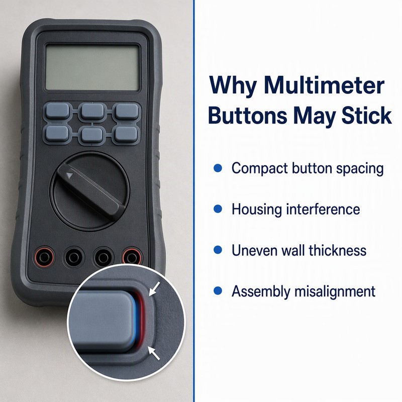
Compact instruments concentrate every tolerance into a smaller space. A handheld multimeter housing is usually two shells clamped together with screws and snap features, and the clamping force is not distributed evenly across the front face. Keys near the seam or near a screw boss start their life preloaded.
The other factor is layout. Keys are placed around the selector and the jacks, and the shape left over for the keypad is rarely a clean rectangle. Irregular layouts produce keys with different amounts of surrounding material, which behave differently under the same press.
| Constraint on a multimeter panel | Effect on nearby keys | What it changes |
|---|---|---|
| Display window | Cuts the panel area available above the keys | Cap height and legend size, not pitch |
| Rotary selector | Takes volume behind the panel and loads keys at rest | Clearance on the selector side and support wall thickness |
| Input jacks | Fix the lower panel boundary | Where the key group can end |
| Shell seam and screw bosses | Apply local clamping force | Which keys start preloaded before the first press |
Compact keypad layouts leave limited space for button movement
Every key needs more space than its visible cap. It needs room for the skirt to deform, room for the cap to rotate slightly, and room for the web to move when the neighbour is pressed. On a multimeter panel that space is being taken by the display window, the selector bezel and the jack rings.
The practical consequence is that keys at the edge of the available area often end up with less surrounding silicone than keys in the middle, because the tool has to fit them into the leftover space. Those keys deform differently, and the difference is felt as a Range or Hold key that is harder to press than the ones beside it.
It is worth measuring the available area before the layout is fixed, rather than after. A keypad area that is a few millimetres short forces compromises in wall thickness and web span that no material choice can recover.
Button openings do not match the actual keypad dimensions
On a compact instrument, the housing opening and the keypad are both small, and the tolerances are a larger fraction of both. A mismatch of a few tenths between the opening pattern and the button pattern is enough to produce contact on one side of every key, in the same direction.
The mismatch often comes from the housing being tooled earlier than the keypad. The keypad is then designed to the housing drawing, which describes nominal dimensions, while the molded housing has its own draft, shrink and parting line offset. The keypad fits the drawing and rubs in the part.
Measuring the actual housing, not only the drawing, closes that gap. On a multimeter, where the front shell and the rear shell both reference the keypad, the measurement should include the assembled front face rather than the bare shell.
Incorrect wall thickness affects button recovery
Wall thickness on a compact keypad is usually set by what will fit, not by what the return stroke needs. A thin wall fills the available space and gives a light press, but it also bends rather than compresses, and bending stores less energy for the return.
Uneven thickness is worse than thin thickness. If one side of the skirt is thicker because a rib or a legend recess runs along it, the button deforms asymmetrically, the cap tilts slightly, and the return is slower on one side. On a small key that asymmetry is felt as a vague press rather than as sticking, which makes it harder to diagnose.
The selector dial area can complicate nearby button placement
The rotary selector is not a flat feature. Behind the dial there is a shaft, a detent mechanism, a stop pawl and usually a switch contact assembly, all of which occupy volume below the panel surface. That volume constrains where a keypad can sit and where its PCB pads can run.
Keys placed inside the arc of the selector often end up with a support wall that is thinner on the selector side, because the tool has to clear the detent housing. That asymmetry is a direct cause of tilt, and it appears only on the keys next to the dial, which is exactly the pattern that makes a technician suspect a single bad switch.
The selector also sets the operating gesture. A thumb rotating the dial rests on the panel beside it, and that resting contact loads the nearest keys laterally, without pressing them. A key that is only just clear at rest will be pushed into contact by that resting thumb, which is a failure mode that no key-press test reproduces.
How to Design Silicone Keypad Structures for Compact Multimeter Housings
Optimize button spacing without sacrificing usability
Silicone keypad design for electronic measuring instruments has to cover two distances: the gap between caps, which is what the finger needs, and the web span between skirts, which is what the material needs. On a compact panel the second is usually the one that is cut, and it is the one that causes neighbour interference.
The deformation zone is the ring around a key in which the silicone moves when that key is pressed.
A useful way to plan it is to draw the deformation zone of each key as a ring around the cap, then check whether the rings overlap. Where they do, the two keys share a load path and should either be moved apart or joined deliberately into one intentional key group.
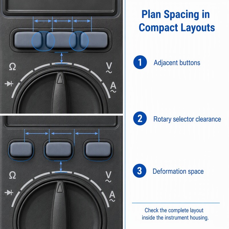
Spacing can be recovered without shrinking keys. Reducing the cap diameter by a small amount while keeping the pitch constant increases both the finger gap and the web span. Reducing the wall thickness does the opposite: it increases deflection under the same load and can close the gap between caps during a press.
Grouping helps as well. A block of four keys that are used together, such as Range, Hold, Min/Max and Relative, can be treated as one group with consistent spacing inside it, while the gap between that group and the selector is made deliberately larger. The operator reads the group, and the material gets a defined boundary to deform within.
Design button height and sidewalls for smooth movement
On a digital multimeter rubber keypad, cap height is usually low, which is good for stability and bad for finger access. The compromise is to keep the cap low but give it a defined edge, so the thumb can find it without looking, and to keep the sidewall short so lateral contact with the opening is limited.
Sidewall contact should be minimized without removing guidance. A short guided section near the base, with the upper sidewall relieved, keeps the button located while reducing the area that can rub. This is one of the few changes that improves both friction and tilt at the same time.
Travel should be consistent across the key group. If one key has more travel than its neighbours because the housing opening is deeper there, the press feels different even when the domes are identical, and the operator interprets that as a sticky key.
Select appropriate dome geometry for different button functions
Multimeter keys fall into three functional groups, and they do not need the same action. Range and function selection keys are pressed repeatedly during a measurement and benefit from a short, light action with a clear breakover. Hold and Min/Max are pressed once per measurement and can be firmer. The power key, which is often pressed with a deliberate hold, benefits from a longer travel and a more definite stop.
Different domes in one tool change the fill pattern and the cavity layout, but they are normal in instrument keypads. The important thing is to decide the groups before the cavity layout is fixed, because adding a dome variant later means a new tool.
Dome geometry also affects how the key behaves when pressed off-center, which on a compact panel is the normal case. A dome that is small relative to the cap leaves the perimeter unsupported, and an edge press then loads the cap rather than the dome.
Keep conductive contacts aligned with the PCB
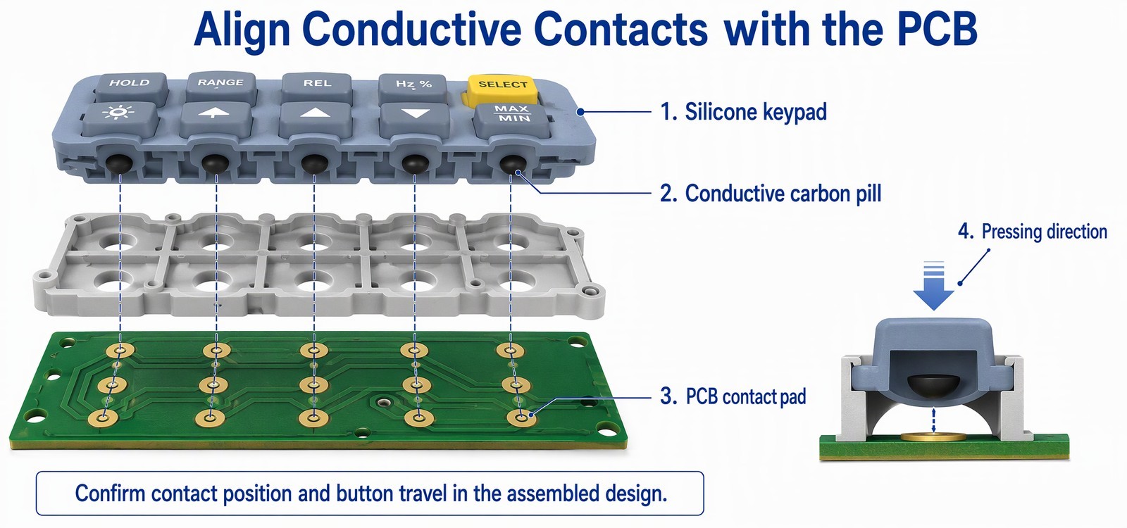
The pill pattern is molded, the pad pattern is etched, and the two are aligned by the assembly. On a compact meter the pads are close together, so lateral movement of the cap during an off-center press matters more than on a larger instrument: a pill that shifts can land partly off its pad or, in a tight layout, close to a neighbouring trace.
Two checks are worth doing on the drawing. First, confirm that each pill is centered under the centroid of its button's pressing area, not under the cap center. Second, confirm that the gap between adjacent pads is larger than the worst-case lateral movement of a pill, which can be estimated from cap diameter, cap height and the clearance in the opening.
Contact closure and tactile breakover are separate criteria and should be reported separately. A key that clicks clearly but closes late will feel fine and work intermittently, which is the hardest failure to diagnose in the field.
How Material Selection Influences Digital Multimeter Keypad Performance
Select silicone hardness based on button dimensions
Custom silicone buttons with thin walls need a softer compound to reach a usable press force, but softer material also deforms more under the clamping load of a two-shell housing. On a compact meter, that clamping load is applied close to the keys, so the material has less room to be soft.
The usual resolution is to keep the compound in a middle band and recover the feel through geometry: a slightly larger dome, a shorter sidewall, or a small increase in cap height where the housing allows. This keeps the return force adequate while keeping the press light.
Balance flexibility and dimensional stability
Flexibility is needed for the press, stability is needed for the fit. On a compact keypad the two requirements meet in the same few millimetres of skirt, so the design has to be efficient: as much of the wall as possible doing structural work, and as little as possible doing nothing.
Dimensional stability also depends on how the part is supported in the housing. A keypad that is located by its outer edge and clamped by the front shell is more stable than one that relies on the buttons themselves to center it, which is a common shortcut on small instruments and a common cause of sticking.
On a compact panel, hardness spread matters more than the nominal value. The compound summary FromRubber publishes for a 70 Shore A material gives hardness 70 ± 5, tensile strength 5.0 MPa required with 5.7 MPa achieved, and elongation at break 150 percent required with 266 percent achieved. Across a small keypad with short travel, a few points of hardness difference is a larger fraction of the total press force than it would be on a large panel, which is one reason two meters of the same model can feel different. Keeping the compound in one controlled band is more useful than chasing a single hardness number.
Consider the actual operating environment
Multimeters are used outdoors, in cabinets, in vehicles and on industrial floors. Temperature swings change silicone stiffness, and a keypad that feels correct at room temperature can feel stiff in a cold van and vague in a hot enclosure. The change is small in absolute terms and noticeable on a key with a very short travel.
Handling conditions matter as much. A meter is often held in one hand while probes are positioned with the other, which means the housing is squeezed while keys are pressed. Cleaning is usually a wipe with a solvent, and the legend and surface finish have to survive it. These are ordinary requirements, and they should be stated rather than assumed.
How Manufacturers Can Reduce Button Sticking During Custom Production
Review keypad and enclosure dimensions before mold development
Rubber keypad sticking is usually decided here, so the review should compare the measured housing, not only the drawing, against the planned button pattern. Button diameter, opening size, cap height, pitch and the distance to the selector bezel are the five dimensions that decide whether the panel will stick.
Interference points should be identified on the assembled model: the selector detent housing, the screw bosses, the shell seam, the display frame and the jack bodies. On a multimeter these are all within a few millimetres of the keypad, and any one of them can preload a key.
Control molding quality around button edges
Flash at the base of a button is the most common molding defect that causes sticking on a compact keypad, because the clearance is small and the flash is irregular. The parting line should sit below the button's guided section, and trimming should be inspected at the button base rather than only at the plate edge.
Incomplete fill shows up differently: a slightly rounded or short button top, or a thin sidewall on the side furthest from the gate. Both change the feel and both are visible under low-angle light before they are visible in a measurement.
Inspect dimensional consistency across multiple keypad cavities
A multimeter keypad tool typically carries several cavities, and cavity-to-cavity variation in button diameter is what produces a batch where some panels stick and others do not. The inspection plan should measure the same key in every cavity, at the same points, on parts from the start and end of a production run.
Button height and dome thickness belong in the same plan. Height variation across a panel is felt as inconsistent feel, and dome thickness variation is felt as inconsistent force, and both are usually present together when the fill is unbalanced.
Validate button movement after complete assembly
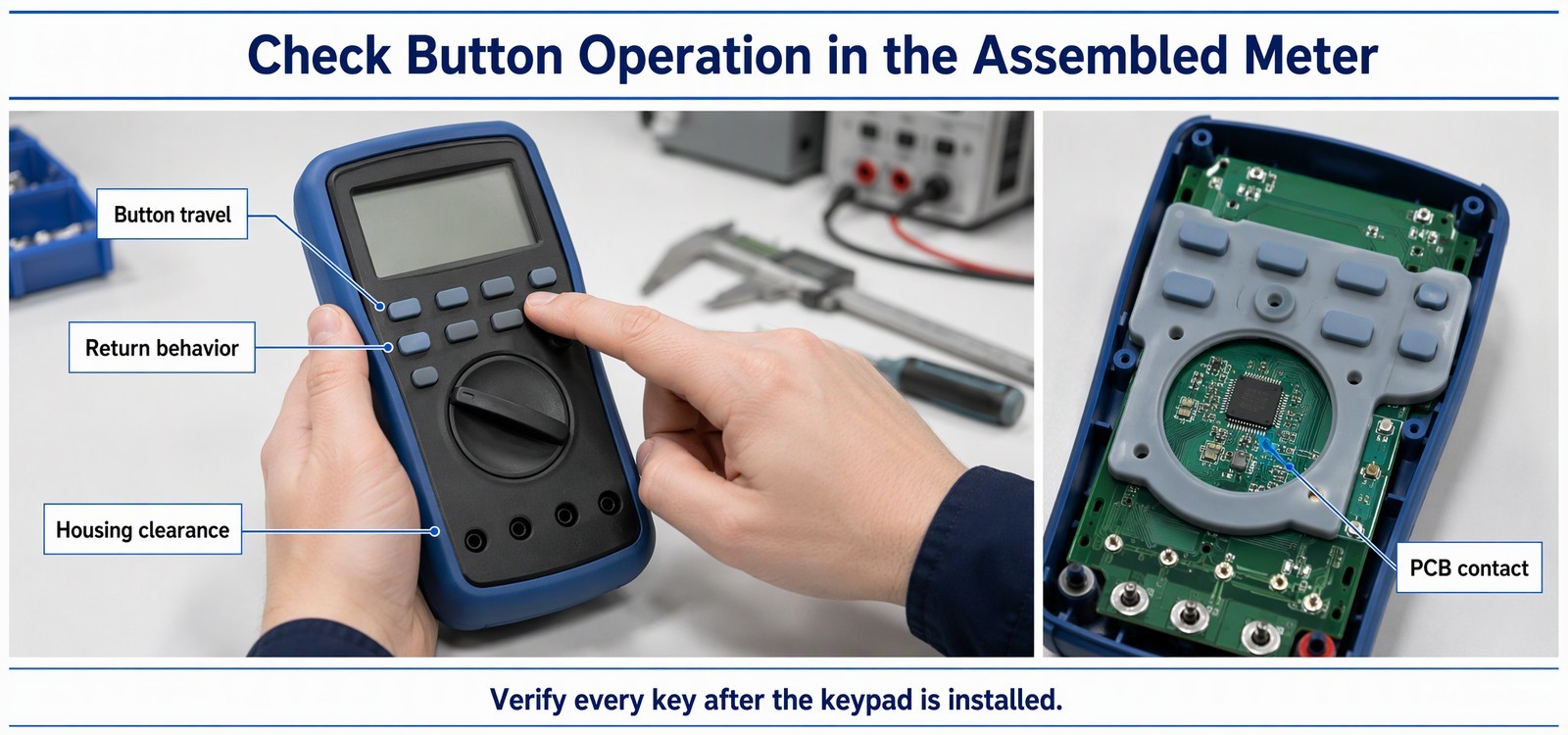
To prevent button sticking in digital multimeters, assembly validation should include the rotary selector in its range of positions, because the detent mechanism moves and can change the clearance behind nearby keys. Press each key with the selector at both ends of its travel and confirm that the feel does not change.
The final check is a full key sweep with the cover fitted and the screws at production torque. Any key that behaves differently from its neighbours at that point has a stack problem, and it will behave the same way in the field.
What Should Buyers Provide When Customizing Digital Multimeter Keypads?
Multimeter housing drawings and keypad dimensions
The front shell drawing with opening dimensions and tolerances, the depth from the front face to the PCB, the selector center and its bezel diameter, and the jack positions. A measured sample of the housing is more useful than a drawing alone on a compact instrument.
PCB contact design and electrical switching requirements
The pad layout with diameters and spacing, which keys use carbon pills, and whether any key needs a metal dome or a membrane layer. The expected closure point in the travel should be stated if the firmware depends on it.
Button specifications and material preferences
Cap dimensions, pitch, height, hardness expectations, color, and the legend method for each key. On a multimeter the legends are usually symbols rather than words, which makes molded or laser-etched marks attractive because there is no ink edge to blur on a small key.
Prototype testing and production requirements
Sample quantity, whether samples are for fit or for life testing, the expected annual volume, and the acceptance criteria. On a compact instrument it is worth asking for samples that can be assembled into a real housing rather than loose keypads, because the assembly is where the sticking appears.
The compact-panel checklist
Measure the housing, not only the drawing. Draw the deformation zone around every key and check for overlap. Keep the gap to the selector bezel larger than the gap between keys. Confirm the pill pattern against the pad pattern with lateral movement in mind. Test every key with the cover fitted and the selector at both ends of its travel.
Frequently Asked Questions About Digital Multimeter Silicone Keypads
Why do digital multimeter buttons become difficult to press?
Usually because the button has started to rub against the housing opening or its support wall. On a compact meter the clearance is small, and clamping from the two shells or movement of the selector mechanism can close it. Material set is possible but less common than interference.
Can silicone hardness affect keypad sticking?
It can contribute. A softer compound deforms more under clamping load and has less return force, so a key that is already close to its opening may begin to hang. Changing hardness without changing clearance usually moves the symptom rather than removing it.
How can manufacturers prevent adjacent multimeter buttons from interfering with each other?
By keeping the web span between keys large enough for the deformation, and by checking whether the deformation zones of adjacent keys overlap. Where they do, increasing pitch or reducing cap diameter is more effective than reducing wall thickness.
Can custom silicone keypads be designed for different multimeter housing structures?
Yes. The keypad is designed from the housing opening and the PCB layout, so different shell designs lead to different keypad geometry. What matters is that the housing is measured rather than assumed, and that the assembly is tested with the selector and the cover in place.
Where the compact panel is decided
On a digital multimeter, sticking is usually a layout outcome. The key that fails is the one that was placed in the space left over after the display, the selector and the jacks were positioned, and it fails because its clearance and its web span were both smaller than the rest of the panel.
FromRubber (Dongguan Bohao Electronic Technology Co., Ltd.) molds custom silicone keypads for handheld measuring instruments, including custom rubber keypads for multimeters with panels laid out around rotary selectors, carbon pill contacts and molded symbol legends. Tooling and sampling are handled in-house, so pitch, cap height and dome geometry can be adjusted at the prototype stage. Quality systems: ISO 9001:2015 and IATF 16949:2016.
For a compact meter panel with a key that needs two presses, send the measured housing dimensions and the pad layout: contact the FromRubber engineering team. Instrument and meter keypads are grouped under custom silicone rubber meter instrument keypads. WhatsApp and WeChat: +86 18676210913.
Sources and supporting reading
Designing a keypad around a rotary selector?
Send the measured housing, the selector center and bezel diameter, and the pad layout. The review covers spacing, deformation overlap and clearance before tooling.
Send the panel layout