Industrial Silicone Gaskets for Equipment Covers: How to Design Custom Shapes for Complex Interfaces
- Share
- Issue Time
- Nov 5,2026
Summary
Irregular covers fail because the gasket is drawn to the cover silhouette instead of the machined land. This article covers the two-line test, bolt interruptions, stepped surfaces, compression variation across a large cover and how to verify a sample in the real assembly.
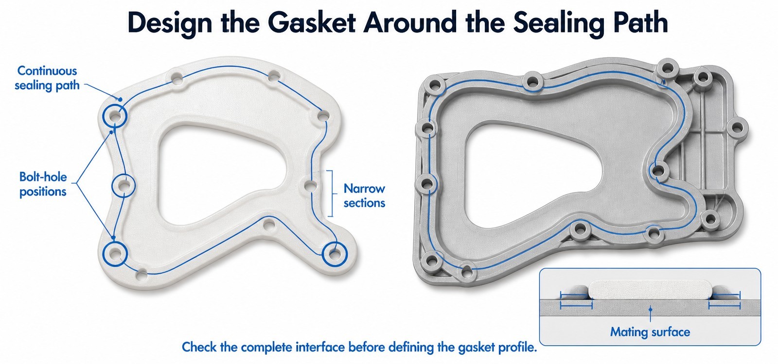
The question arrives with a photograph: can you make a gasket in this shape? The shape is the cover. That is the problem.
On a cast equipment cover, the outer edge is a manufacturing convenience — it is where the casting ends. The sealing surface is somewhere inside it, usually where the machined land is, and the two lines almost never coincide. A gasket drawn to the cover outline will look right in a render and fail on the first assembly, because most of its length is pressing on a surface that was never machined to seal.
Complex covers are not difficult because the outline is complicated. They are difficult because there are two closed loops in the design — the loop the gasket must seal, and the loop the fasteners occupy — and the gasket has to satisfy both while staying manufacturable.
Why Do Standard Silicone Gaskets Fail to Fit Complex Equipment Covers?
The Cover Has an Irregular or Asymmetrical Outline
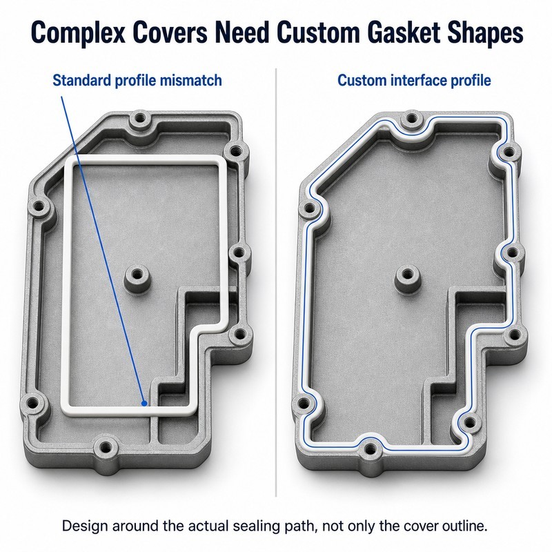
A standard rectangular or circular gasket assumes the sealing path is a regular closed curve. On an equipment cover with a cut-off corner, a connector cut-out or a stepped edge, it is not. The standard part crosses empty surface at each deviation, and every crossing is a place where the gasket is compressed against air.
The reverse error is just as common: a gasket that follows the cover outline exactly will run along the thin outer wall of a casting, where there is no machined land and often a draft angle. It seals on a slope.
Multiple Bolt Holes Interrupt the Sealing Path
Bolts do two conflicting things to a gasket. They provide the compression that makes it seal, and they remove the material that would otherwise carry that compression. Every hole in a gasket is a place where the sealing path has to divert around a void and where the local width drops.
On a cover with an uneven bolt pattern — some holes close together, some far apart — the gasket has to be narrow in one place and can be wide in another. A constant-width gasket either crowds the close holes or wastes material where nothing needs sealing.
The Sealing Surface Contains Steps or Height Differences
A flat gasket can only seal a flat surface. Where a cover has a step, a raised boss, or two lands at different heights, a constant-thickness part will contact the high land and float over the low one. The result is a gasket that is fully compressed in one region and untouched in another, which reads as a material problem and is a geometry problem.
The two-line test
Before drawing any gasket, mark two closed loops on the cover: the sealing line, where the machined land runs, and the fastening line, where the bolts sit. If the sealing line passes outside the fastening line anywhere, that section will lift when the cover is pressurised or handled. If it passes inside by less than the local material width, the gasket will be too narrow to seal there. Both conditions are visible on the drawing and invisible in CAD unless someone looks for them.
How Should a Custom Silicone Gasket Be Designed for an Irregular Interface?
Define the Actual Sealing Path Before Designing the Outer Profile
Start from the mating surface. The sealing path is the continuous band of machined or flat surface that surrounds whatever has to be kept in or out — oil, water, dust, or an internal volume. Its inner boundary and outer boundary exist on the cover whether or not anyone has drawn them.
Trace that band, then check its width at the narrowest point. The gasket must fit inside it with margin, which means the narrowest point sets the maximum gasket width for the whole loop, not just for that section.
Match the Gasket Shape to the Contact Surface
Where the land runs straight, the gasket runs straight. Where the land turns a corner, the gasket follows the radius rather than cutting the corner. Where the land steps in height, the gasket either follows the step with a moulded transition or the design is split into two gaskets — a decision that should be taken deliberately rather than discovered at assembly.
The most common error in irregular gaskets is smoothing a complex path into something easier to draw. Every smoothed section puts the gasket somewhere the land is not.
Maintain Sufficient Material Around Holes and Narrow Sections
Around a bolt hole, the gasket has a ligament between the hole edge and the outer or inner edge of the sealing band. If that ligament is thin, the gasket tears at the hole during assembly, or stretches as the bolt pulls it into line. The ligament also has to carry the compression load from the bolt into the sealing band.
Where a hole sits close to the sealing path, the practical options are a local thickening — a pad around the hole — or a moulded boss that moves the load path away from the thin section. Both change the profile, which is why this decision belongs in the design rather than in the tooling.
Should You Use a Flat Gasket or a Custom Molded Silicone Profile?
When a Flat Silicone Gasket Is Suitable
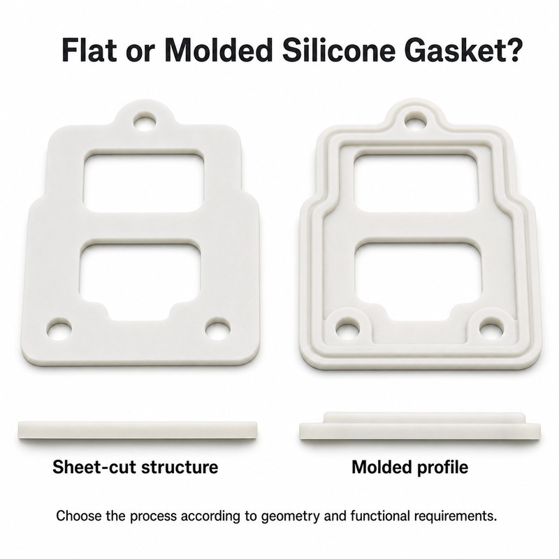
A flat gasket cut from sheet works well when the land is genuinely flat and wide, the cover is stiff, the bolt spacing is close enough to keep deflection small, and the whole interface sits in one plane. It is cheap to tool, fast to sample, and easy to revise — which makes it a good choice for low volumes and for designs that are still moving.
Its limits are equally clear. It cannot follow a step, it cannot provide its own location, and it has no feature to stop it being installed the wrong way round.
When a Molded Profile Offers More Design Flexibility
A moulded gasket can carry a raised sealing rib that concentrates pressure on a narrow land, a locating edge that drops into a groove, pads around bolt holes, or a stepped section that matches a stepped cover. Once the tool exists, these features cost almost nothing per part.
The trade-off is commitment. A mould is a decision that is expensive to reverse, so the design has to be settled before the steel is cut — which is exactly the point at which many projects are still changing.
How to Choose Between Die-Cut and Molded Gasket Structures
Use die-cutting when the geometry is two-dimensional and the function is only sealing. Use moulding when the gasket has to do a second job — locate itself, tolerate a step, resist extrusion into a gap, or provide a defined contact band narrower than the land.
A useful test is to ask what happens if the gasket is installed upside down. If the answer is "nothing changes", a flat part is adequate. If the answer is "it leaks", the design needs a feature, and a feature needs a mould.
| Criterion | Flat die-cut gasket | Moulded profile |
|---|---|---|
| Interface shape | One flat plane of adequate width | Steps, bosses and narrow lands |
| Location at assembly | Needs a groove or a fixture | Can locate itself with a moulded edge |
| Revision cost | Low and fast to sample | Requires a tool change |
| Height change across the cover | Cannot follow | Followed with a moulded transition |
How Do Gasket Width and Thickness Affect Complex Sealing Interfaces?
Select Width Based on the Available Contact Area
On a complex cover the width available changes around the loop. The gasket has to be narrow enough for the tightest section and wide enough elsewhere to seal a land that may be pitted or scratched. In practice this means designing to the minimum, then checking that the resulting contact pressure is adequate where the land is widest and the cover is least stiff.
Match Thickness to the Gap Between Equipment Components
Thickness has to account for the closed gap at its widest, including casting tolerance, machining tolerance and cover deflection under bolt load. On a large cover, deflection between bolts can be a significant part of the total gap, and a gasket sized from the machined dimensions alone will be under-compressed in the middle of each span.
Consider Different Compression Conditions Across the Interface
Compression is never uniform on a large cover. It is highest at the bolts and lowest midway between them, and it is lower still where the cover is unsupported. A gasket designed for average compression will be over-compressed in some places and under-compressed in others.
The design response is compliance rather than hardness: a section that can deflect locally without generating excessive pressure, so that the variation across the interface stays inside the range the material can tolerate.
How Can Custom Silicone Gaskets Be Positioned Accurately During Assembly?
Add Locating Holes or Positioning Features Where Needed
Locating features exist to remove judgement from the assembly line. A gasket that can only fit one way — because one hole is offset, or because a tab engages a slot — is assembled correctly by default, including by someone who has never seen the product before.
Use Retaining Grooves or Molded Edges to Prevent Displacement
Where a cover is assembled vertically or overhead, gravity is enough to drop a loose gasket out of position before the first bolt is fitted. A groove with a retaining lip, or a moulded edge that clips over the land, keeps the part in place. The cost is tooling complexity; the benefit is that the leak you never see does not happen.
Check Whether the Gasket Can Be Installed Without Stretching
A gasket stretched during installation stays slightly longer than its groove and sits in waves. On a complex outline, those waves concentrate at the corners, which is already the hardest part of the loop to seal. If the part has to be stretched to fit, the gasket is the wrong size, not the wrong material.
What Information Should Equipment Manufacturers Provide for Custom Gasket Development?
Equipment Cover and Mating-Surface Drawings
Send both halves of the interface, not only the cover. The sealing path is defined by the pair: the land on the cover and the surface it presses against. A drawing of one side describes half the problem.
Bolt Hole Positions and Critical Sealing Dimensions
Give the bolt pattern with position tolerances, the width of the machined land, the depth of any groove, and the flatness of the land. Flatness is the dimension most often omitted and most often responsible for a leak between bolts.
Operating Temperature and Environmental Requirements
State the temperature range in operation and in cleaning, and the media the gasket will see — oils, coolants, wash chemicals, steam, UV. Silicone covers a wide temperature range but a narrow one in oil, so this single answer often decides the material before any geometry is discussed.
Required Material Hardness and Functional Performance
Describe what the seal has to achieve rather than the hardness you want. "Must seal against IPX4 spray with a 0.4 mm cover deflection between bolts" tells a moulder far more than a Shore A figure, and it lets the geometry and the compound be chosen together.
How Should Custom Industrial Silicone Gasket Samples Be Verified?
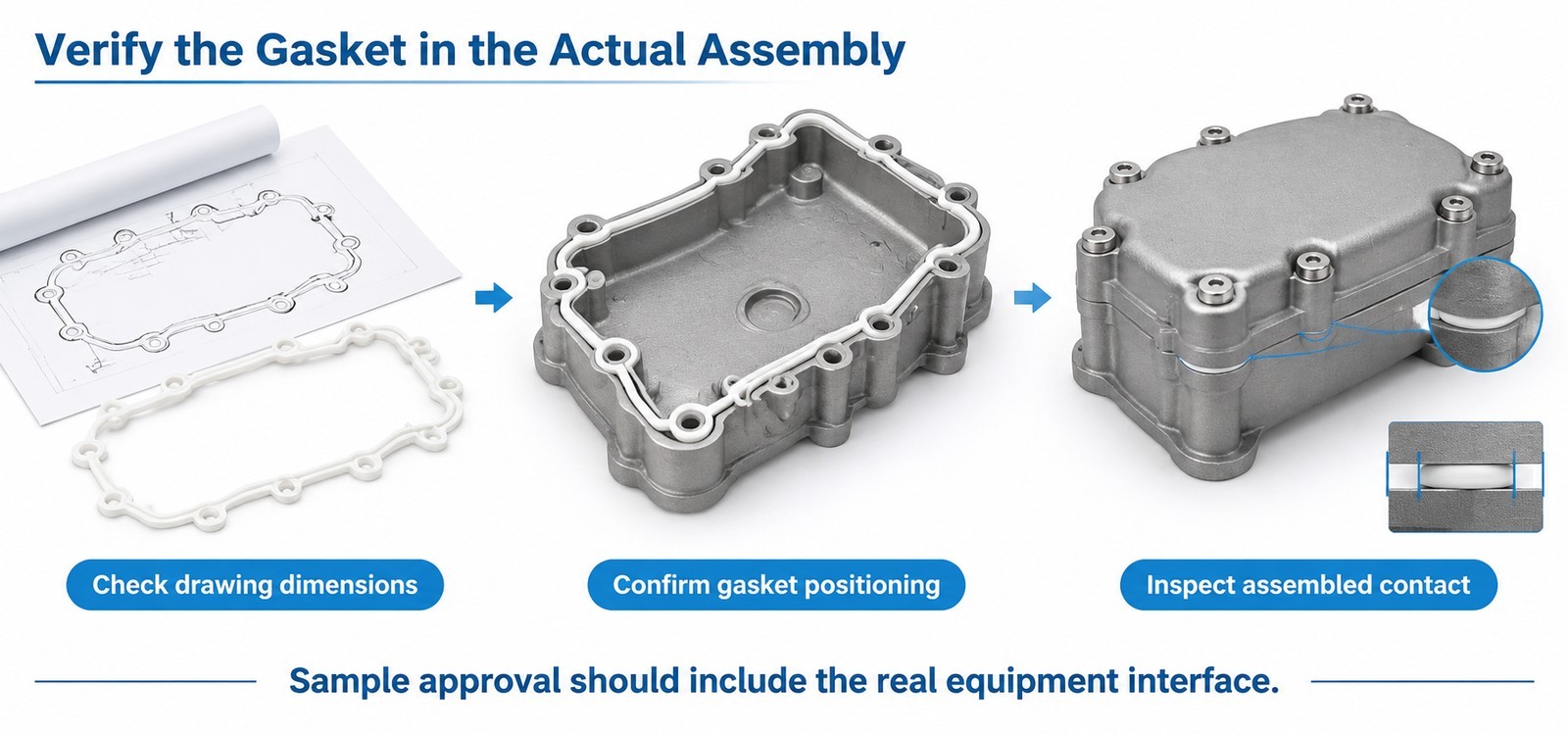
Compare the Sample With the Approved Technical Drawing
Check the profile, the hole positions, the thickness and the narrow ligaments. Hole positions matter more than overall outline on a complex gasket, because a small positional error changes where the gasket sits relative to the land.
Install the Gasket on the Actual Equipment Cover
Fit it dry, without fasteners, and look for gaps between gasket and land. Then fit the fasteners finger-tight and look again. Anywhere the gasket lifts is a place where the sealing path and the gasket path disagree.
Inspect Compression and Contact Along the Sealing Path
Use pressure-sensitive film or a soft shim between gasket and land, then read the imprint. The pattern shows the true compression distribution — including the areas that looked fine and were never touching.
Test Sealing Performance Under Actual Application Conditions
Where the enclosure has an ingress protection target, the test method and severities come from IEC 60529, and the whole enclosure has to meet them. The gasket is one contributor: a good gasket on a housing with a gap at a cable entry will still fail, and the result will be blamed on the gasket.
Custom Industrial Silicone Gasket Manufacturing at FromRubber
FromRubber has been moulding custom silicone parts in Dongguan since 2010, across two plants with 32 compression moulding machines (30 vacuum-assisted, 2 plate presses), a seven-machine CNC tool shop and inspection, working to IATF 16949:2016, ISO 9001:2015 and ISO 14001:2015. Irregular gaskets — asymmetric outlines, multiple holes, stepped lands — make up a steady part of that work.
The engineering step that matters most here is reading the interface rather than the outline. That means checking the sealing path against the machined land, identifying the narrowest ligament around each hole, and confirming where the parting line will fall relative to the contact face. Where a customer has a casting but no reliable drawing, the land can be measured and the gasket profile rebuilt from it.
We will not claim that a custom shape guarantees a dry enclosure. The gasket can only seal the surface it is given; if the land is interrupted or the cover deflects beyond what the section can absorb, the honest answer is to change the cover or the fastening, and that conversation is better had before tooling.
Frequently Asked Questions About Custom Industrial Silicone Gaskets
Can silicone gaskets be made in irregular shapes?
Yes. Asymmetric outlines, internal cut-outs and offset holes are routine in compression moulding. The practical constraints are the width of the sealing land, the narrowest ligament around a hole, and whether the section can turn the tightest corner without collapsing.
Are molded silicone gaskets better than flat silicone gaskets?
Neither is better in general. Flat gaskets suit flat, wide lands and simple outlines; moulded gaskets suit steps, narrow lands, and interfaces where the gasket also has to locate itself. The choice follows the interface.
How do I design a silicone gasket for a multi-hole equipment cover?
Start from the sealing path between the holes rather than the hole pattern. Keep a consistent ligament around each hole, allow extra width where holes sit close to the land, and check that bolt tightening will not pull the gasket off the path.
How can I prevent a custom silicone gasket from moving during assembly?
Give it somewhere to sit and only one way to fit: a retaining groove, a moulded edge, an offset locating hole or a tab. Features that make the part impossible to install incorrectly are more reliable than assembly instructions.
What drawings are needed to manufacture a custom industrial silicone gasket?
Both mating surfaces, the machined land with its width and flatness, the bolt pattern with position tolerances, the closed gap, and the operating media and temperature. A gasket outline on its own is not enough to design the part.
Draw the Sealing Path, Not the Silhouette
A complex cover is a test of whether the sealing line was read correctly. Once that line is on the drawing, with its narrowest width and its bolt interruptions marked, the rest of the design follows — profile, thickness, location features and tooling.
Send both halves of the interface, even as photographs with a scale, and we will tell you where the path is too narrow or too far from the fasteners. WeChat and WhatsApp: +86 18676210913.
Sources
- IEC 60529 — Degrees of protection provided by enclosures (IP Code), IEC Webstore.
- Elastic recovery after compression in HNBR at low and moderate temperatures, Polymer Testing 61 (2017), SINTEF — compression set and elastic recovery in elastomer seals.