Internal Resistance Tester Silicone Button: Achieving 500,000+ Cycle Life for Professional Use
- Share
- publisher
- Suey
- Issue Time
- Apr 21,2026
Summary
A cycle count says nothing about when an internal resistance tester silicone button stops being accurate. This brief treats contact resistance drift as the real end-of-life metric, explains how to measure it with a four-wire setup, and shows how dome geometry, carbon pill formulation and actuator force decide whether a keypad still reads 20 milliohms at cycle 400,000.
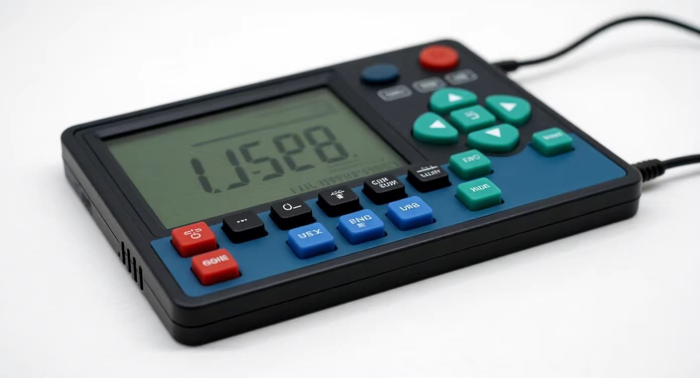
Measurement brief
An internal resistance tester silicone button does not fail when it stops clicking; it fails when its contact resistance drifts far enough to bias the measurement the instrument exists to make. That makes end of life a milliohm threshold, not a cycle count. Specifying the threshold, the measurement current and the actuation force turns a marketing number into a testable requirement.
- Define end of life as a resistance limit at a stated force — for example 50 milliohms at 250 grams — not as a click tally.
- Four-wire Kelvin measurement removes lead and trace resistance, which otherwise swamp a single-digit ohm reading.
- Drift comes from the interface: pill wear, contamination and dome relaxation, not from the silicone body.
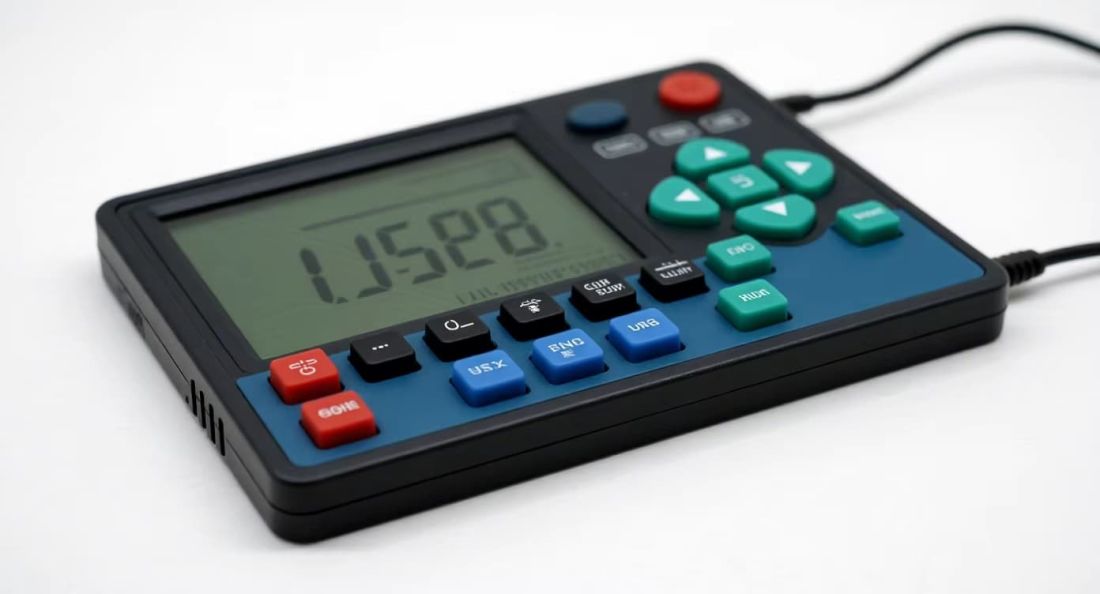
Why an internal resistance tester silicone button fails by drift, not by click count
A rubber key with a conductive pill closes a circuit across a pair of interdigitated traces. Every actuation burnishes the pill, transfers a little contamination from the finger side, and relaxes the dome slightly. None of these events stops the key working; each of them raises the resistance the instrument sees. At some point the offset is larger than the resolution the tester claims, and calibration starts chasing a moving target.
The practical consequence is that a 500,000-cycle claim is only meaningful next to a resistance ceiling. Two keypads can both survive half a million presses while one has drifted from 12 to 30 milliohms and the other from 12 to 180. The first is a lifetime; the second is a slow calibration failure that shows up as disputed readings in the field.
How to measure contact resistance on a silicone button
Use four wires: force current through the pill and the trace pair with one set of leads, and sense voltage with another pair placed inside the current path. Two-wire measurements include the probe contact and the lead resistance, which on a 20 milliohm target is most of the reading.
Then fix the force. Resistance is a function of contact pressure, so a measurement at 100 grams and a measurement at 400 grams are different tests. Pick a force that matches the actuator your product uses, hold it for a defined settle time, and report the curve rather than a single point. A force-resistance sweep at 50, 100, 200 and 400 grams exposes a pill that only conducts when it is nearly crushed.
- Constant current source — 1 to 10 milliamps, low enough not to heat the interface.
- Fixed actuation force — stated in grams, applied by a motorised stand rather than a thumb.
- Settle time — 50 to 200 milliseconds, recorded, because resistance falls as the contact beds in.
- Log every 10,000 cycles — the trend matters more than the endpoint.
Design variables that decide how long the button stays in specification
Each row is a decision on the drawing or in the compound specification, and each one moves the drift curve.
| Variable | Effect on resistance drift | What to specify |
|---|---|---|
| Carbon pill formulation | Softer pills bed in faster but wear quicker | Conductive carbon-loaded silicone with a stated hardness range |
| Pill diameter versus trace pitch | Too small concentrates force and wears the trace | Pill at least 1.5 times the trace pitch |
| Dome geometry and travel | Short travel reduces wiping, leaving contamination in place | Travel and snap ratio defined in the drawing |
| Actuator hardness | Hard actuators transfer shock to the pill | Shore A range agreed with the housing design |
| Sealing membrane | Adds force loss and traps debris | State the force budget across the full stack |
Writing the acceptance test into the purchase specification
A purchase specification that says “minimum 500,000 cycles” invites a test that counts presses until the key stops responding, which is a durability test for the wrong failure. Replace it with three statements: the resistance ceiling at a defined force, the number of cycles over which that ceiling must hold, and the sampling interval at which resistance is recorded.
Add the environmental preconditioning that matches the product. A bench instrument in a temperature-controlled lab sees a different life than a tester used on a workshop floor next to a battery charger. Cyclic humidity followed by a resistance sweep catches moisture ingress that a dry cycle test never will, and it is the failure mode that produces the most confusing field complaints.
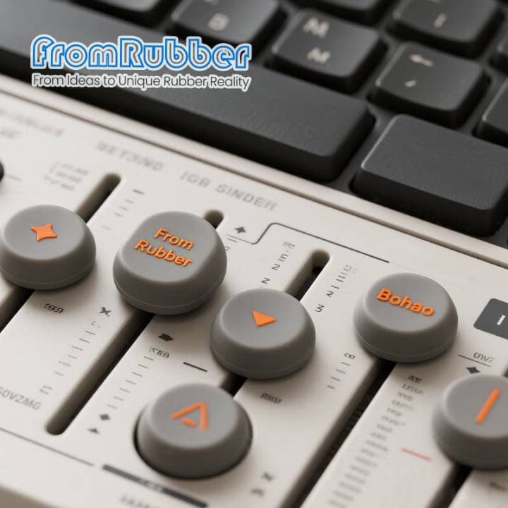
How keypad drift shows up in resistance test data
A milliohm-level drift on a keypad looks like a calibration problem long before anyone suspects the button. The symptom is a small offset that appears when an operator presses ENTER and disappears when the same measurement runs from the front-panel software. If the offset correlates with one key rather than with one channel, the contact resistance of that key is the first thing to measure.
The diagnostic is cheap: bridge the key with a known resistor and repeat the reading. If the error follows the key and not the fixture, the keypad is out of specification. Keep a log of contact resistance at each calibration interval, and the drift becomes a trend line you can act on instead of a mystery that costs a day of technician time.
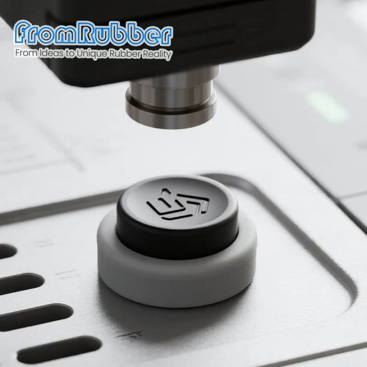
Questions about button life and contact resistance
Is a higher cycle rating always better?
Only with a resistance ceiling attached. A keypad rated for a million presses that drifts past the instrument's error budget at 200,000 is worse for a calibration lab than one rated for 500,000 that holds its value.
Should we specify gold-plated contacts?
Gold helps when the trace side is the limiting factor and the environment is corrosive. It does not fix a pill that is too small or an actuator that hammers the contact. Fix geometry first, then plating.
Why does resistance rise after humidity testing?
Moisture films the interface and, in a sealed keypad, condenses on the coldest surface. The film adds a resistive layer that the actuation force may not break through. A vented or better-sealed design resolves it more reliably than a harder pill.
How many samples does a cycle test need?
Six to ten units from a production tool, tested to failure rather than to a pass mark. The spread between units tells you whether the process is controlled; the mean tells you very little on its own.
Specify the resistance, and we will build the keypad to hold it
FromRubber moulds conductive silicone keypads and buttons with defined pill geometry, dome travel and actuator hardness, and can supply cycle data with resistance logged at intervals. Send the trace layout, the actuator force and the accuracy your instrument claims; we will propose a contact design and a test plan that supports it.
Request a keypad design reviewRelated reading: why battery tester silicone buttons outlast rubber and custom silicone rubber keypads.