Quick Tip: How to Avoid Uneven Thickness When Designing Silicone Makeup Tools
- Share
- Issue Time
- Nov 9,2026
Summary
Uneven wall thickness is the most common reason a silicone makeup tool needs a second tooling round. This design review explains where material accumulates at corners, how thin walls fail at ejection, why gradual transitions are easier to mold, and which sections to check before the mold is cut.
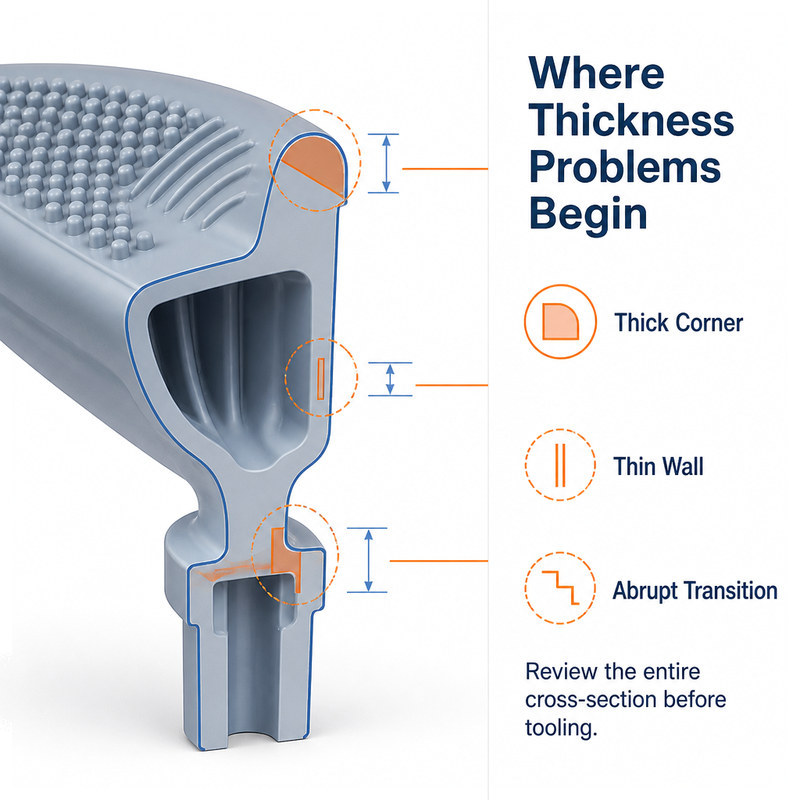
The first sample of a silicone makeup tool arrives, and the part is not the shape on the drawing. A corner has sunk slightly. A thin rim has pulled away from where it should sit. The toolmaker says the mold is correct, the molder says the compound is correct, and both are right. The problem was fixed into the design before either of them touched it: the wall thickness was not even enough for a single molding cycle to cure the whole part at one time.
Uneven thickness is one of the most common reasons a silicone makeup tool needs a second tooling round. It is also one of the few problems that can be solved on a screen, before any steel is cut, if the designer knows where to look.
Why Uneven Thickness Is a Common Design Problem in Silicone Makeup Tools
Beauty tools are shaped by use, not by manufacturing. A spatula needs a thin scraping edge and a rigid handle. A sponge holder needs a firm base and a soft opening lip. A brush cleaning mat needs thick areas for structure and thin, springy walls where water has to pass. Every one of those requirements pulls material into uneven sections, and each uneven section becomes a place where heat, pressure, and material flow behave differently from their neighbours.
The three review areas on a typical beauty tool: material accumulating at a corner, a wall thinned by a groove, and a step where a handle meets a head.
The usual hot spots are consistent across products: the inside of a corner where two thick walls meet, the neck between a handle and a head, the rim around an opening, and the floor of a recessed logo. Designers look at these areas as features. A mold sees them as material that has to be heated through, and as a place where the part will either cure too long or release too early.
The consequence is not only cosmetic. Thick sections can show sink or internal voids. Thin sections can tear at ejection or stay under-cured and lose elasticity. And because a mold is cut to nominal dimensions, every thickness variation in the design becomes a variation in the finished part, which then has to be absorbed by a tolerance class. Dimensional tolerances for moulded rubber products are defined in ISO 3302-1, and a design that forces a part into a tighter class than it needs is buying cost it will not use.
Identify High-Risk Areas Before Finalizing the Product Design
Thick Sections Around Corners and Connecting Areas
Material accumulates at inside corners for a purely geometric reason: the outer surface has further to travel than the inner surface, so any corner with a generous outer radius and a tight inner radius has more material in the diagonal than in either wall. On a silicone part this shows up as a locally stiff block that cures slower than the surrounding wall.
The risk increases when two thick sections meet at an abrupt angle. A designer who needs a rigid joint will often thicken both arms, which doubles the accumulated mass at the joint. The fix is usually not to thin the arms but to change the transition: extend the thicker section into the thin one over a longer distance so the heat path has somewhere to go.
Thin Sections Around Grooves, Edges, and Openings
Thin walls fail differently. A groove that is narrow at the bottom needs a thin steel rib in the cavity, and that rib is the first part of the tool to wear or break. An edge thinner than the rest of the wall cools faster, cures faster, and can be over-cured by the time the thick section is ready, which makes it brittle right where the part flexes. On openings, the thin band between the hole and the outer edge becomes the tear initiation point during demolding.
Our notes on tear strength in ultra-thin silicone walls describe the same mechanism on a different product: when the wall is thin enough, tear resistance stops being a material property and becomes a geometry and ejection problem.
Uneven Thickness in Raised and Recessed Features
A raised logo, a textured pad, or a recessed ring changes the cross-section in a way that is invisible from the outside. A 0.4 mm raised letter sits on top of a wall that is already 2.5 mm thick, so the section behind the letter is 2.9 mm and cures last. A recessed ring removes material and creates a thin floor. Neither feature looks risky in a rendering, and both change the thermal map of the part.
This is the reason a design review should look at sections, not surfaces. A section drawing takes ten minutes to produce and can remove an entire sample round.
Use Gradual Thickness Transitions Instead of Abrupt Changes
Where a thickness change is unavoidable, spread it. A gradual transition does three useful things at once: it gives heat a continuous path, it avoids a stress concentration at the step, and it lets material flow evenly instead of hesitating at a shoulder.
In practice, a gradual transition means extending the change over a distance that is visibly longer than the thickness difference, with a radius at both ends. Designers sometimes resist this because it looks less crisp on a rendering. On a molded part, the gradual version usually looks better in production, because the alternative is a visible step combined with a sink mark or a flow line.
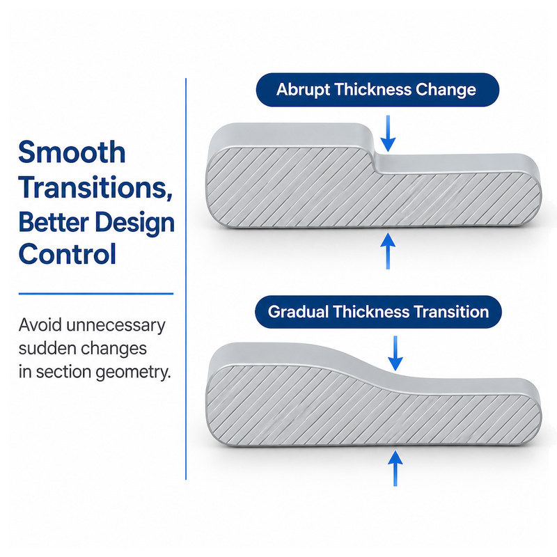
Same part, two transitions. The upper geometry forces heat through a step; the lower one spreads the change over a distance, which is easier to cure and easier to eject.
Review the whole part rather than isolated sections. A single transition can be perfectly designed and still fail, because the section on the far side of the part is competing for the same cure time. The question is not "is this wall too thick" but "is this the thickest wall on the part, and what does that force the cycle to be".
Keep Product Geometry Consistent Around Functional Areas
Design Balanced Thickness Around Openings and Edges
An opening is a structural interruption. A cut-out in a mat, a slot in an organizer, or a hole in a holder all remove material from exactly the place that resists deformation. If the band around the opening is thinner than the surrounding wall, the opening becomes a hinge, and the part will bend there whether or not that was the intent.
A practical rule is to keep the band around an opening at least as thick as the adjacent wall, and to round the transition into the wider body. If the opening has to be sharp-edged for functional reasons, the wall behind it should be allowed to be slightly thicker, not thinner.
Avoid Excessive Material at the Base and Connection Points
The base of a holder is where designers tend to add mass for stability, and it is also the slowest-curing region of the part. Adding 2 mm of material at the bottom to stop a wobble can add several seconds to every cycle and still not fix the stability problem, because stability depends on the contact area and the height of the centre of gravity, not on how much material sits in the base.
Balance support and flexibility deliberately. If a section is meant to flex, give it a consistent thin section with rounded transitions. If a section is meant to hold its shape, give it thickness and shorten its unsupported span. Mixing the two in one region produces a part that is neither stiff nor flexible, and a mold that has to compromise on cure time.
How Uneven Thickness Can Affect Silicone Molding Results
Compression molding relies on heat transfer through the material while the mold is closed. A thick region takes longer to reach cure temperature at its core than a thin region does. Because the mold closes once and opens once, the cycle is set by the slowest region. The thin region is therefore exposed to heat for longer than it needs, and the thick region is released as soon as it is just cured.
That imbalance shows up in predictable ways: dimensional variation between parts, a surface that looks slightly different in thick areas, flash that behaves differently around the perimeter, and occasionally a part that passes first-article inspection and then drifts during a long run. None of these are guaranteed defects. They are the range of outcomes a mold has to control when the section is uneven, and the control cost appears in cycle time, scrap rate, and inspection effort.
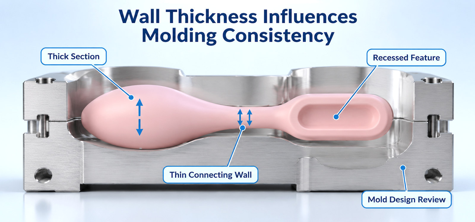
In compression molding, the cycle is set by the slowest section. A thick base and a thin connecting wall in the same part cannot both be ideal, so the design has to keep the difference inside a workable range.
Our notes on how mold design and parting lines affect the finished appearance cover the same interaction from the tooling side. It is worth being precise here: actual results depend on compound formulation, mold design, press settings, and the part's own geometry. Uneven thickness does not automatically produce a bad part. It removes the margin, and margin is what keeps a production run stable on an ordinary day.
What Should Be Checked During the Mold Design Stage?
By the time a mold is being designed, the part geometry is mostly fixed, so the review is about confirming that the geometry can be molded as drawn. A short, ordered check catches most issues:
- read the cross-sectional drawing, not only the outside view;
- mark the thickest and thinnest sections and calculate the ratio between them;
- check the transitions around functional areas: openings, rims, joints, and the base;
- review the parting line position and the areas where flash will form;
- confirm the geometry suits compression molding, including draft and ejection;
- approve a prototype sample against the critical dimensions and the intended flexibility.
Parting line and flash deserve their own line in that list because they interact with thickness. A parting line placed on a thin edge produces a fragile edge that is difficult to deflash without tearing. Our article on silicone mold parting line design and flash control covers that interaction in more detail.
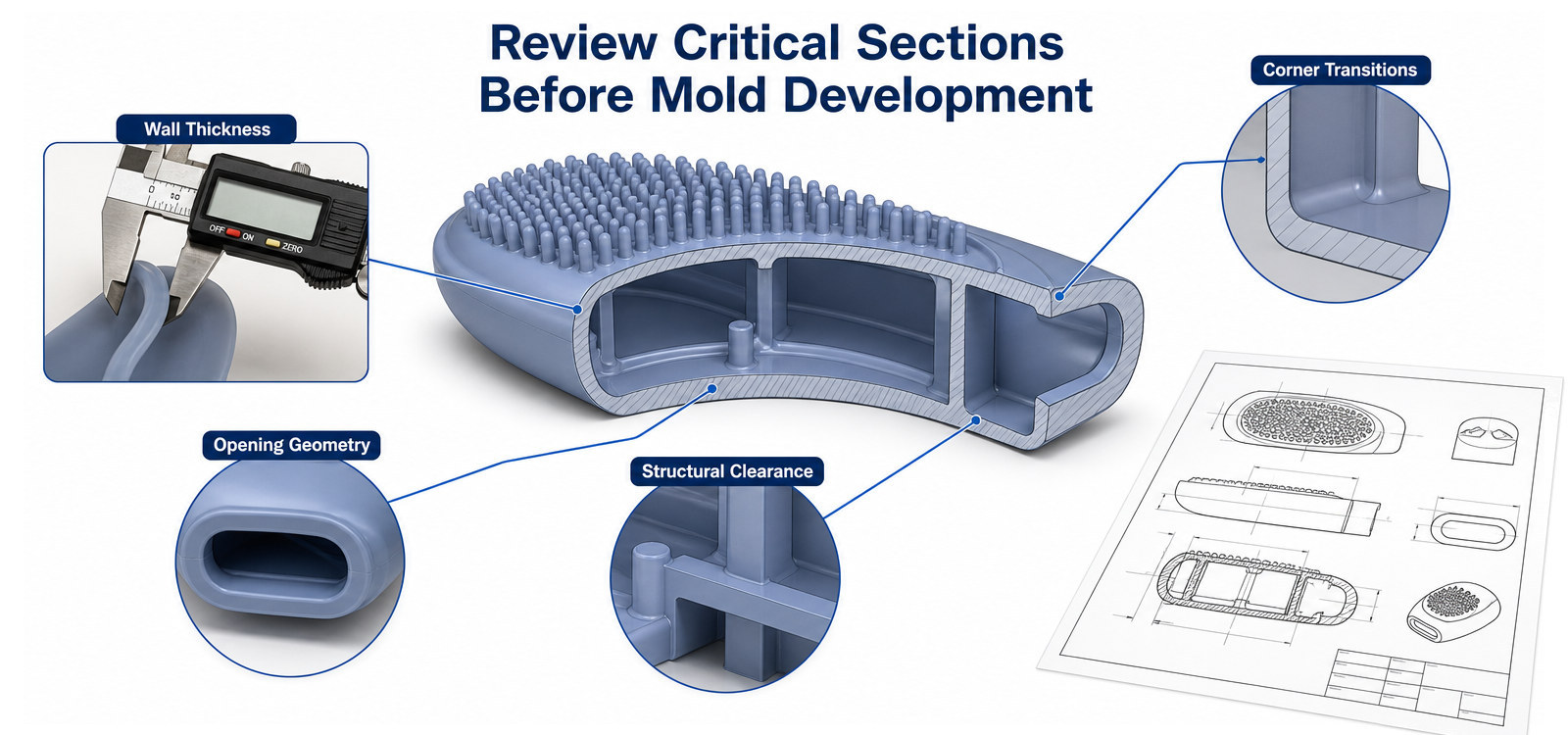
A pre-mold review reads the section, not the surface. Caliper checks, corner transitions and opening geometry all come from the same drawing, and each one can change the tooling plan.
A Practical Thickness Design Checklist for Custom Silicone Makeup Tools
| Check | Why it matters at the mold stage |
|---|---|
| No unnecessary sudden steps in wall thickness | Steps concentrate stress and create a slow-curing mass |
| Enough material around openings and joints | Prevents the opening from acting as a hinge or tear point |
| No excess thickness in flexible sections | Keeps the intended function and avoids a stiff, slow-curing block |
| Internal and external geometry both reviewed | The inside of a part is where thickness problems usually hide |
| Feasibility confirmed with the molder before tooling | A five-minute review can remove a tooling revision later |
| Critical dimensions identified before sampling | Turns first-article approval into a measurement task, not an opinion |
Get Engineering Support Before Developing Your Custom Silicone Makeup Tools
Thickness review is one of the few engineering tasks that costs almost nothing at the design stage and a great deal after tooling. A manufacturer who molds beauty tools every week can usually point at the problem area from a section view in a single conversation, because the failure pattern repeats across products.
FromRubber works with beauty brands and OEM buyers on custom silicone makeup tools, from concept review through tooling and production. Engineering consultation, 10 CNC machines for mold work, and 40 compression molding machines sit in the same facility, so a change to the wall section does not have to travel through three suppliers before it is tested. You can send 2D drawings, 3D models, or a physical sample through the inquiry form, or discuss it directly on WhatsApp and WeChat at +86 18676210913.
Frequently asked questions
What thickness ratio is acceptable in a molded silicone part?
The acceptable ratio depends on the compound, the part size, and the process, so it should be confirmed with the molder rather than assumed from a general rule. What matters at the design stage is knowing the ratio and deciding whether the thickest section is doing useful work.
Can a thick section be fixed by extending the cycle time?
Extending the cycle can cure the thick section, but it over-cures the thin sections and raises cost on every part. It is a compensation, not a design solution, and it usually shows up later as a brittle edge or a dimension that drifts.
Does a sink mark on a silicone part mean the mold is wrong?
Not necessarily. Sink is usually a section-thickness signal. The mold may be dimensionally correct while the part's section design leaves a mass that shrinks differently from the surrounding wall.
Is uneven thickness a problem for small parts too?
Yes, and often a bigger one. On a small part, a 1 mm difference is a large percentage of the wall, and the ratio between the thickest and thinnest section is what drives the molding window.
What should a buyer send for a thickness review?
A section view plus the 3D model is ideal. If only a 3D model exists, note where the part must be stiff and where it must flex, because that intent decides which sections can be adjusted.
Sources and further reading
- ISO 3302-1:2014, Rubber, Tolerances for products, Part 1: Dimensional tolerances. ISO 3302-1 standard page (https://www.iso.org/standard/62492.html)
- ASTM D2240-15(2021), Standard Test Method for Rubber Property, Durometer Hardness. ASTM D2240 standard page (https://store.astm.org/d2240-15r21.html)
- FromRubber technical notes: parting line design and flash control, tear strength in ultra-thin silicone walls.