Silicone Gasket Thickness: How Does It Affect Compression, Sealing and Service Life?
- Share
- Issue Time
- Nov 3,2026
Summary
Thickness is how much compression travel a joint has available, not a measure of seal quality. This article explains compressed thickness, builds a four-line gap budget, shows why both thin and thick gaskets leak in opposite ways, and describes how thickness is confirmed on a sample rather than assumed from a drawing.
Two units came back from the same production run with the same complaint: water in the housing. Both had a 3 mm gasket. One had been crushed until the rubber was 1.9 mm and had started to lift at the corners. The other had only been compressed to 2.8 mm and had never made contact along one edge.
Same part number, same thickness, two opposite failures. That is the useful lesson about silicone gasket thickness: thickness on its own is not a sealing parameter. It is the amount of travel you have bought. Whether that travel gets used depends on the gap between the parts, the tolerance on both of them, and how much force the joint can apply.
This article looks at thickness as a budget rather than a dimension, and at the point where adding another half millimetre stops helping.
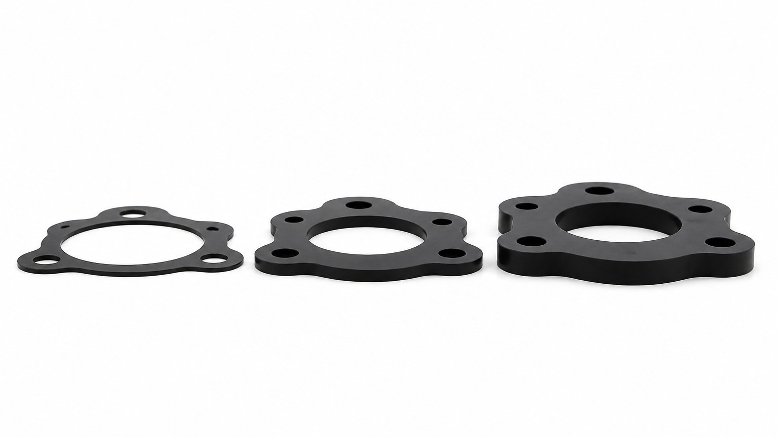
The three gaskets below share an outline and differ only in thickness. From the side, the difference looks trivial. In a joint, it changes the bolt load, the compression ratio, and whether the cover can close at all.
When a joint leaks, the question is rarely "is the gasket thick enough". It is "how much of this thickness is being used, and where".
The number that actually governs the seal
What the rubber experiences is not free thickness but compressed thickness — the dimension it is reduced to when the joint is closed. Silicone gasket compression is therefore the design variable, and compression ratio is simply how much of the free thickness was used:
compression ratio = (free thickness - compressed thickness) / free thickness, expressed as a percentage
A 2 mm gasket closed to 1.5 mm is at 25% compression. A 4 mm gasket closed to 3.5 mm is at 12.5%. The second one is thicker and less compressed, which is why a thick gasket can leak in a joint where a thin one sealed.
The useful framing is that the joint, not the gasket, decides the compressed thickness. The gasket only decides whether the resulting compression falls inside a workable band.
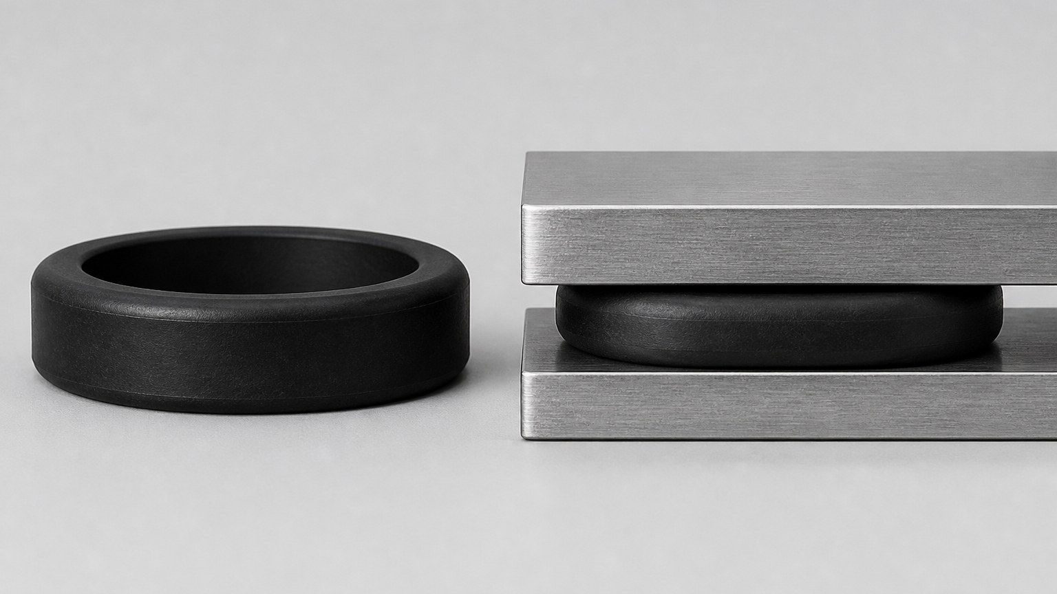
Here is the same gasket in both states. On the left it is at free thickness. On the right it is closed between plates, with the section flattened and slightly wider.
Reading a joint this way makes the design question concrete: what compressed thickness will this assembly produce, and is that inside the range the material can hold over time?
When the gasket is too thin
The joint runs out of compression travel
A thin gasket has little travel to give. That is a problem as soon as the gap is not uniform.
If the mating faces vary by 0.2 mm and the gasket can only accommodate 0.3 mm of compression before going solid, the margin is gone. The tight corner reaches full compression while the loose corner is still unloaded, and the joint seals in one place and leaks in another. Nothing about the gasket is defective; it simply ran out of range.
Thin sections are harder to handle and to hold tolerance
Thin gaskets are also harder to handle. A 1 mm section has little stiffness of its own, so it folds, rolls, and drops out of a groove during assembly — the positioning problem that shows up later as a leak. And around mounting holes, a thin section leaves less material to resist tearing during installation.
There is a second-order effect that is easy to miss: manufacturing tolerance becomes proportionally larger as thickness falls. A ±0.10 mm tolerance on a 1 mm gasket is 10%; the same tolerance on a 3 mm gasket is 3%. If the joint has a narrow compression window, a thin gasket spends more of that window on its own tolerance.
When the gasket is too thick
The excess material has to go somewhere
The opposite failure is less intuitive and more damaging, because it usually looks like success at first: the joint closes, the gasket fills the gap, and the leak test passes on the bench.
What happens is that a thick gasket needs more force to reach the intended compression, and the joint has to supply it. If the cover is thin, the cover deflects instead. The middle of the joint then sits at lower compression than the edges, and the seal band becomes uneven. If the cover is stiff and the fasteners are strong, the force goes into the gasket instead, and the material at the tightest point is compressed past its working range.
Over-compression produces three visible symptoms. The gasket bulges sideways out of the groove. The edges lift slightly where the material has been displaced. And the section thins permanently, so the second assembly has less material to compress than the first. All three reduce the seal rather than improve it.
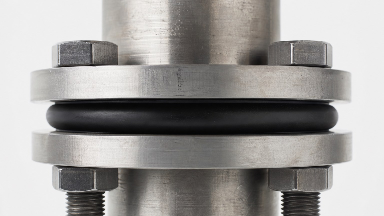
The flange below shows the bulge clearly. The gasket is thicker than the space available, so the excess material has to go somewhere, and it goes outward past the flange face.
In a joint with a groove, that same excess material is trapped, which is worse: it loads the groove walls, distorts the cover, and can shear the gasket when the joint is opened.
| Thickness result | What you see on the joint | Usual cause |
|---|---|---|
| Too thin | Contact marks missing at the loose corner; gasket flattened and glossy at the tight one | Gap variation exceeds the compression travel available |
| Correct | Continuous contact band around the perimeter, cover sits flat | Thickness matched to the measured gap, not the nominal drawing |
| Too thick | Gasket bulges out of the groove; cover bows between fasteners | Thickness exceeds the clearance the joint can close |
Building a gap budget before choosing a thickness
The reliable way to choose thickness is to add up everything that consumes compression travel, then pick a thickness that leaves a usable margin. The budget has four lines:
- Nominal gap between the mating faces with the joint closed and no gasket present.
- Flatness and step variation across both faces, taken from the drawing tolerance or measured on the parts.
- Deflection under load — how much the cover or housing moves when the fasteners are tightened.
- Gasket thickness tolerance, which for moulded silicone follows the ISO 3302-1 classes; a 20 mm dimension at M2 is roughly ±0.25 mm, and thickness tolerances scale with section size.
The gasket has to be thick enough that the loosest point still gets useful compression, and thin enough that the tightest point does not exceed the material's working range. For a static flange joint, that range is commonly 20–30% compression, which is a wide enough window to absorb a normal tolerance stack — but not a stack that includes a warped cover and a 0.4 mm step.
A quick sanity check on any proposed thickness
Take the nominal gap, add the worst-case variation, and subtract the gasket's low tolerance limit. That is the maximum compression the tightest point will see. Then take the nominal gap, subtract the worst-case variation, and subtract the gasket's high limit: that is the minimum compression at the loosest point. If either number falls outside the working band, changing the thickness will not fix it — the joint geometry has to change.
Why the compression curve matters more than a rule of thumb
Rules of thumb about compression percentages are useful as a starting point and misleading as a specification, because the force needed to reach a given compression depends on hardness and section shape, not only on thickness.
A 60 Shore A gasket at 25% compression can require several times the force of a 40 Shore A gasket of the same dimensions at the same compression. In a joint with fixed bolt torque, that difference decides whether the cover closes properly. This is why thickness and hardness have to be chosen together: a thicker gasket at lower hardness can behave like a thinner gasket at higher hardness in terms of force, while giving more travel.
Section shape matters too. A gasket with a raised sealing lip reaches a given contact pressure at lower total force than a flat section, because the loaded area is smaller. On a joint that cannot take much clamping force, changing the profile is often more effective than changing the thickness.
What thickness does to long-term sealing
Compression set takes back the margin
Compression set is the slow loss of thickness under sustained load, and it is the reason a joint that passed at assembly can leak a year later. The thicker the gasket and the higher the compression, the more absolute material is lost to set — even when the percentage looks acceptable.
That matters for serviceable products. If the cover will be opened twice a year, the gasket has to come back close to its original thickness each time. A joint designed at the top of the compression band will lose that ability faster than one designed in the middle, regardless of thickness. Our notes on compression set and rebound loss cover the mechanism from the material side, and the same behaviour applies to a static gasket sitting under a bolted cover.
How we set thickness on a new joint
When a customer sends a housing drawing without a gasket thickness, the first step is not to pick a number. It is to calculate what the assembly will do to whatever number we pick. That means the nominal gap, the tolerance on both faces, the fastener arrangement, and the stiffness of the cover.
From there we choose a starting section, mould a prototype in the intended compound, and measure the compressed thickness at several points around the perimeter after assembly. If the spread is wider than the working band, the answer is usually a profile change or a joint change rather than a thickness change.
Dimensions on the tool are built with shrinkage compensation — silicone moves roughly 1.5% to 3% during cure depending on compound and section — and thickness is verified on the first article rather than assumed from the drawing. Our plant in Dongguan runs 32 compression presses with the tool shop in the same building, which shortens the loop when a thickness or groove change has to be tried.
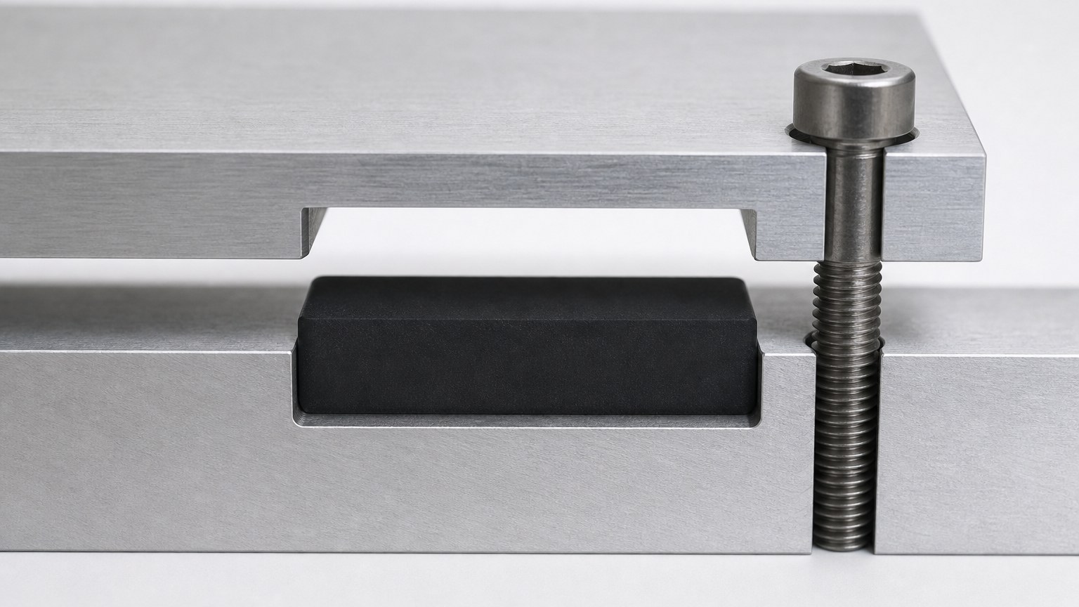
This is the relationship that a thickness number has to satisfy. The groove depth, the gasket thickness and the cover position together decide the compression; the gasket alone decides almost nothing.
If you are specifying a gasket for a joint like this, the drawing should show the groove depth and the closed gap, not only the gasket section. Without those two dimensions, any thickness is a guess that happens to be written down.
In short
Thickness is how much compression travel the joint has available, not a measure of seal quality. Too thin and the joint runs out of travel before it reaches the loose corner; too thick and the joint runs out of space, bowing the cover or over-compressing the tight corner. The working point sits between those, set by the gap budget and confirmed by measuring a sample in the real housing.
Send the housing drawing, the closed gap and the fastening detail through our inquiry page and we will work the compression range back from the assembly. If the numbers do not close, we will say so before a tool is cut. Email: nani@fromrubber.com or karl@fromrubber.com. WhatsApp and WeChat: +86 18676210913.
Common questions about gasket thickness
How thick should a silicone gasket be?
Thick enough that the loosest point of the joint still reaches 20–30% compression, and thin enough that the tightest point stays inside the material's working range. The number comes from the measured gap, not from a catalogue.
What compression ratio should a silicone gasket run at?
Static flange joints commonly run 20–30%. Below that, surface variation is not absorbed and the contact band breaks up; well above it, the material takes compression set and may extrude sideways.
Why does a thicker gasket sometimes leak more?
Because it needs more force to compress. If the cover is thin it deflects instead of compressing the seal, the mid-span loses contact, and the contact pressure becomes uneven around the perimeter.