Silicone Keypad PCB Assembly: The Ultimate Troubleshooting Guide for Conductive Contact Failure & Carbon Pill Misalignment
- Share
- publisher
- Suey
- Issue Time
- Jul 14,2026
Summary
A comprehensive engineering guide to diagnosing and solving conductive contact failure and carbon pill misalignment in silicone keypad PCB assemblies. Covers failure modes, silicone oil contamination, post-curing protocols, force-displacement validation, and real-world solutions from a leading silicone keypad manufacturer.
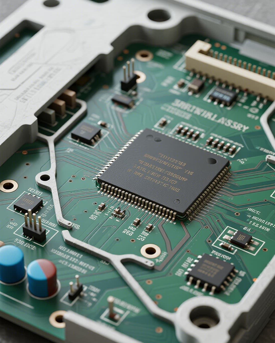
The Hidden Problem Behind Unresponsive Keypads
Have you ever pressed a button on a remote control or industrial device, only to find it unresponsive — not because the battery is dead, but because the internal conductive mechanism has silently failed? This frustrating and often puzzling issue is far more common than most engineers expect. Behind every silicone keypad that gradually loses sensitivity lies a complex interplay of material science, contamination mechanics, and assembly tolerances that can make or break the electrical connection between the key and the circuit board.
The statistics from field returns tell a sobering story: over 60% of silicone keypad failures are traceable not to component wear, but to conductive contact failure at the carbon pill-PCB interface. These failures manifest as intermittent response, increased actuation force requirements, or complete key dropout — each of which can bring consumer electronics returns or, in industrial settings, costly production line stoppages.
Understanding Conductive Contact Mechanisms in Silicone Keypads
To diagnose contact failure, we must first understand how a silicone keypad creates an electrical circuit. When a key is pressed, the conductive element on the underside of the silicone dome — typically a carbon pill, gold pill, or conductive ink layer — bridges two interdigitated (interlocking finger) traces on the PCB. This momentary short circuit is detected by the device's microcontroller as a key press.
The total contact resistance (Rtotal) is the sum of three components:
- Rpill_bulk — Volumetric resistance through the pill itself, typically 5–50 Ω for carbon pills
- Rinterface — Constriction resistance at the pill-PCB contact interface, typically 10–100 Ω on ENIG gold surfaces
- Rtrace — PCB copper trace resistance, typically negligible
Industry standards require Rtotal below 200 Ω for new keypads, with high-reliability medical and aerospace applications specifying below 100 Ω. After 1 million actuation cycles, contact resistance should not increase by more than 100% from the initial value. When this threshold is breached, the microcontroller fails to register the key press reliably.
Key Insight: The carbon pill-PCB contact interface is where silicone rubber keyboards either succeed or fail electrically. Careful material selection, pill geometry design, PCB finish specification, and firmware debouncing together determine switching reliability across the product's rated lifecycle.
Common Failure Modes in Silicone Keypad PCB Assembly
Field experience and laboratory analysis have identified several recurring failure mechanisms that plague silicone keypad assemblies. Each failure mode has distinct root causes and requires targeted countermeasures.
Pill Delamination
The carbon pill separates from the silicone key dome due to inadequate bonding during molding. This occurs when the mold temperature profile fails to achieve full cure at the pill-silicone interface, or when post-bonding processes are substituted for insert molding. Mitigation: Use insert molding where the pill is placed in the mold before silicone injection, and ensure mold temperature profiles reach complete vulcanization at the interface.
Contact Contamination
Dust particles, silicone oil migration from the key mat, and environmental contaminants create a high-resistance barrier layer between the pill and PCB traces. This is the single most common cause of intermittent keypad failure globally. Mitigation: Specify IP6X dust-tight enclosures, use vented contact patterns, and consider gold-plated PCB contacts with sufficient contact pressure to penetrate light contamination films.
Pill Surface Oxidation
Long-term exposure to elevated temperatures oxidizes the carbon pill surface, progressively increasing contact resistance. The carbon black grades used in pill manufacturing release volatile compounds under heat, and surface oxidation creates a semi-insulating layer. Mitigation: Select acetylene black grades with low volatile content and specify maximum operating temperatures in the product specification.
Mechanical Pill Fracture
Repeated impact stress causes crack initiation and propagation in overly hard or under-cured pill compounds. The pill Shore A hardness should be maintained between 50 and 65 for optimal durability. Mitigation: Verify cure state through differential scanning calorimetry (DSC) and perform lifecycle testing to 1.5 times the rated life.
Why Silicone Oil Migration Destroys Contact Reliability
Among all failure mechanisms, silicone oil migration (also known as silicone bleed-out) is the most insidious and the hardest to diagnose. Low-molecular-weight silicone oligomers — byproducts of incomplete curing — gradually migrate from the silicone key mat to the contact surface. When these adsorbed silicone molecules are subjected to joule heating from closed contacts or arcing during switching, they thermally decompose to form silicon dioxide (SiO2), an electrically insulating glass-like film.
Research published in the IEEE Holm Conference on Electrical Contacts has demonstrated that even monolayer films of SiO2 can increase contact resistance by several orders of magnitude. The growth of this insulating film follows an exponential function of exposure time, silicone concentration, and temperature. Once the SiO2 film thickness exceeds approximately 80 nanometers under light contact loads (below 5 grams), static contact resistance becomes unacceptably high.
The countermeasure is well-established: post-curing at 200°C for 4 hours after primary molding removes the vast majority of free silicone oligomers before they can migrate to contact surfaces. This single process step has been shown to reduce field failure rates from silicone contamination by over 90% in controlled studies.
Carbon Pill Misalignment and Contact Pressure Issues
Even with perfectly cured silicone and clean contacts, the assembly can still fail if the carbon pill does not align correctly with the PCB contact pad. Alignment precision is governed by several factors in the design and assembly stack-up.
| Parameter | Recommended Value | Impact on Reliability |
|---|---|---|
| Contact pad diameter vs. pill diameter | 20–30% larger (e.g., 6–7 mm pad for 5 mm pill) | Accommodates alignment tolerances between silicone mat and PCB |
| Trace width and spacing | 0.25–0.50 mm | Narrower traces reduce debris bridging risk |
| Number of interdigitated finger pairs | 4 to 8 pairs | More fingers provide redundancy against contamination |
| Venting channels | Integrated into contact pattern | Prevents air entrapment causing inconsistent contact |
| PCB finish for carbon contacts | ENIG (gold over nickel) | Lowest contact resistance, excellent wear resistance |
Assembly stack-up tolerance analysis is critical. The cumulative tolerances from the silicone keypad molding, the plastic housing, the PCB thickness, and the assembly press-fitting can easily exceed the available contact overlap. Engineers must account for the entire tolerance chain and ensure that even at worst-case conditions, the carbon pill covers at least 60% of the contact pad area.
Key design parameters to verify:
- Carbon pill contact resistance measured at <100 Ω per key using a four-point probe method
- Force-displacement curve validation to ensure 50–150 gf actuation force with at least 40% snap ratio
- Alignment pins or positioning ribs on the silicone keypad to guarantee alignment accuracy during housing assembly
- Post-curing validation through outgassing testing to confirm free silicone oligomer removal
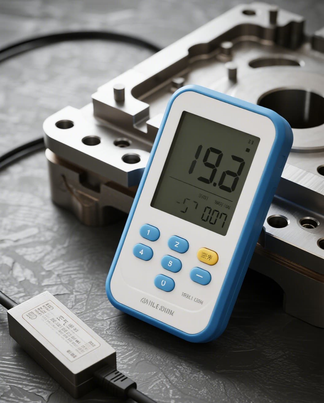
Engineering Solutions for Reliable Keypad Assembly
Building a silicone keypad that performs reliably over millions of cycles requires a holistic approach spanning material selection, mold design, process control, and quality verification. Here are the proven engineering solutions that leading manufacturers implement:
1. Optimized Post-Curing Protocol
Implement a post-curing cycle of 200°C × 4 hours in a forced-air convection oven. This removes free silicone oligomers that cause contact contamination. Verify post-cure effectiveness using thermogravimetric analysis (TGA) to measure weight loss — the target is less than 0.5% volatile content.
2. Precision Tooling for Pill Placement
Design the mold cavities with precisely located pill pockets that center each carbon pill relative to the key dome center. The pocket depth should be 40–60% of the pill thickness to prevent pill shift during the compression molding process. Use optical inspection after pill loading to detect misplacement before molding.
3. Force-Displacement Curve Validation
Every production lot should undergo force-displacement characterization using a compression tester with ±1 gram resolution. The actuation force should fall within ±10% of the design target, and the snap ratio (ratio of actuation force to contact force) must exceed 40% for crisp tactile feedback.
4. Integrated Alignment Features
Design alignment pins or positioning ribs directly into the silicone keypad molding tool. These features engage with corresponding holes or slots in the plastic housing and PCB, guaranteeing sub-millimeter alignment accuracy during final assembly.
Real-World Case Study: Medical Device Keypad Redemption
A leading medical device manufacturer approached FromRubber with a critical problem: their infusion pump keypad was experiencing intermittent contact failure after approximately 300,000 cycles — well short of the 1-million-cycle specification. The root cause investigation revealed three compounding issues:
- Silicone oil contamination: The original supplier had skipped post-curing, leaving high levels of free oligomers in the key mat. These migrated to the carbon pill surface and formed an insulating SiO₂ layer.
- Insufficient pill-to-pad overlap: The PCB contact pad was designed with only 10% diameter margin over the carbon pill. Combined with cumulative assembly tolerances, some keys had as little as 30% effective contact overlap.
- No alignment features: The keypad assembly relied entirely on housing snap-fits for positioning, with no dedicated alignment pins.
The solution: FromRubber redesigned the silicone keypad with integrated alignment pins, increased the carbon pill diameter by 1 mm, and implemented a 200°C × 4-hour post-curing protocol. The PCB contact pad was also redesigned per our recommendations to provide 30% diameter margin. The redesigned keypad achieved 1.5 million cycles with less than 50% increase in contact resistance — exceeding the original specification by 50%.
Result: 50% cycle life improvement, zero field returns in 18 months, and 40% cost optimization through simplified assembly.
PCB Surface Finish Selection for Carbon Contact Reliability
The choice of PCB surface finish is one of the most consequential decisions in silicone keypad design. Different finishes offer vastly different contact resistance, wear resistance, and cost profiles. Here is how the common options compare for carbon pill contacts:
| PCB Finish | Contact Resistance | Wear Resistance | Relative Cost | Best For |
|---|---|---|---|---|
| ENIG (Gold over Nickel) | 15–50 Ω | Excellent | 3× | Medical, aerospace, high-reliability |
| Carbon Ink on PCB | 30–150 Ω | Good | 1× | Consumer, cost-sensitive industrial |
| Silver Ink on PET | 20–80 Ω | Moderate | 1.5× | Flexible circuits, membrane hybrids |
| Immersion Silver | 10–40 Ω | Poor (tarnishes) | 2× | Short-life or sealed enclosures |
| HASL (Tin-Lead) | 50–200 Ω | Poor (oxide growth) | 1× | Not recommended for carbon contacts |
ENIG is the gold standard for silicone keypad contacts. The gold layer (0.05–0.15 microns) provides an oxide-free, low-resistance surface, while the underlying nickel (3–7 microns) serves as a hard diffusion barrier. For cost-sensitive applications, printed carbon ink on FR-4 offers a compatible carbon-to-carbon interface with acceptable performance.
Frequently Asked Questions
Q: Carbon pills vs. gold pills — which is better for my product?
A: The choice depends on your application's electrical requirements and budget. Carbon pills offer a contact resistance of <100 Ω at a lower cost, making them ideal for consumer electronics and most industrial applications. Gold pills provide ultra-low resistance (typically <1 Ω) and are preferred for mission-critical medical devices, aerospace controls, and any application where signal integrity cannot be compromised. For products in corrosive environments, gold pills are strongly recommended due to their tarnish resistance.
Q: How do I test whether the keypad travel is sufficient for reliable contact?
A: The most reliable method is force-displacement curve testing using a compression tester. The curve should show a clear snap-through at the actuation force (typically 100–180 gf) followed by a contact force at the bottom of travel that is at least 60% of the actuation force. The total key travel should be 0.8–2.0 mm. If the curve shows no clear snap or the contact force is too low, the web dome geometry needs adjustment.
Q: Can I fix an existing keypad with contact failure, or do I need a full redesign?
A: In many cases, partial modification is possible. If the failure is due to silicone oil contamination, post-curing the existing keypads at 200°C for 4 hours can often restore acceptable performance. If carbon pill misalignment is the issue, adding alignment features through mold modification may suffice. However, if there are fundamental geometry errors in the web dome or the PCB contact pattern, a full redesign is the only reliable path.
Q: What is the minimum carbon pill contact resistance I should specify?
A: For most applications, specifying a maximum contact resistance of 100 Ω per key (measured at 10–20 gf actuation force using a four-point probe) provides adequate margin. For high-reliability applications, specify 50 Ω maximum and require 100% electrical testing of all keys. Always specify the measurement conditions (force, probe type, environmental conditions) to ensure consistent testing between suppliers.
Conclusion: Building Reliability Into Every Contact
Silicone keypad PCB assembly reliability is not a matter of luck — it is the product of deliberate engineering decisions at every stage of design and manufacturing. From selecting the right carbon pill composition and PCB surface finish to implementing post-curing protocols and precision alignment features, each decision cascades into the final contact performance.
The most reliable silicone keypad assemblies share a common DNA: adequate post-curing to eliminate silicone oil migration, generous pill-to-pad overlap to absorb alignment tolerances, rigorous force-displacement characterization, and integrated alignment features that guarantee repeatable assembly precision. By applying these engineering principles, manufacturers can achieve contact resistance stability through millions of cycles and eliminate field failures caused by conductive contact degradation.
For engineers facing keypad reliability challenges, the fastest path to resolution is a systematic root-cause analysis that examines the entire assembly stack — from pill chemistry through PCB finish to housing tolerances. Sending your PCB layout files for a free assembly evaluation can identify potential failure points before they become field problems. Our engineering team at FromRubber specializes in solving these exact challenges with over a decade of silicone keypad manufacturing expertise.