Silicone Keypad for Rebar Scanner: How to Design Keypads for Concrete Inspection
- Share
- publisher
- FromRubber
- Issue Time
- Sep 10,2026
Summary
A rebar scanner is operated with gloved hands on a concrete site - and its silicone keypad has to stay findable, pressable and durable through a full inspection grid. This article looks at the documented silicone keypad of the TMTeck TMRS-710, tactile feedback, sealing and the electrical interface, and how a custom keypad is developed for NDT equipment.
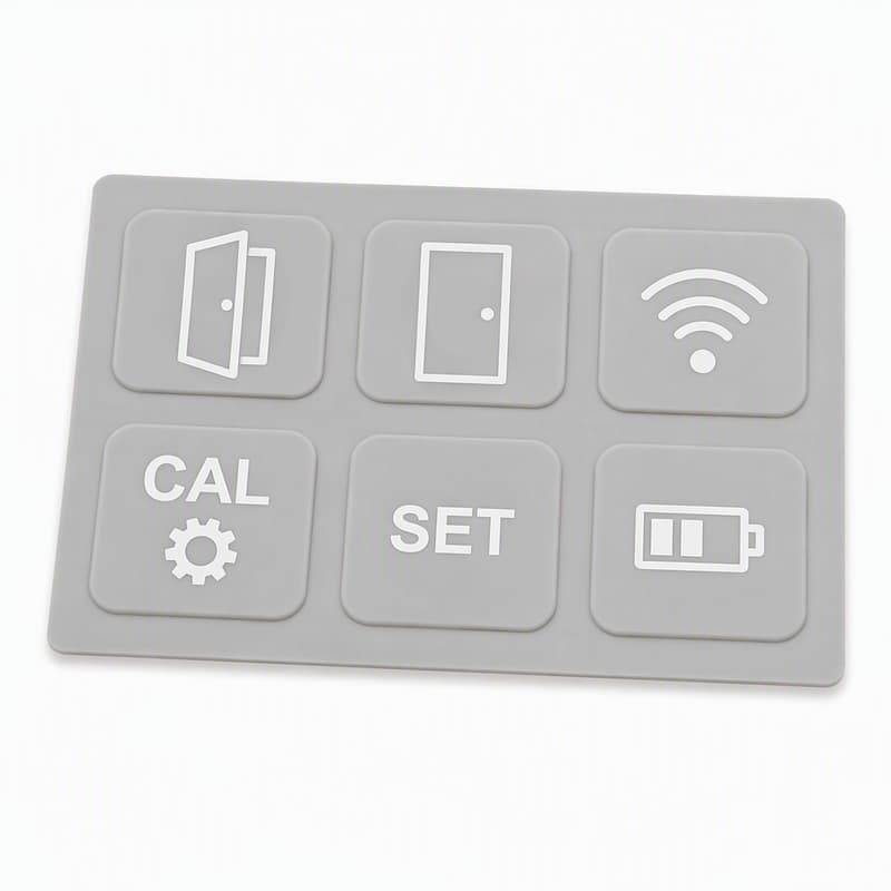
A rebar scanner is carried onto a concrete slab, into a formwork bay or up a parking structure, and the operator's hands are holding a grid of reinforcement that is not visible through the concrete. The instrument has to be scanned across the surface, adjusted between passes and read without taking eyes off the display — and the silicone keypad for rebar scanner projects carries all of that input. When the keys are hard to feel through a glove, or the pad wears after a season of site use, the inspection workflow slows down at the worst possible moment: in the field, halfway through a scan grid.
What Is a Silicone Keypad for Rebar Scanner?
From a manufacturer's perspective, a silicone keypad for a rebar scanner is a single molded silicone part with five functional zones. The silicone body forms the continuous base that carries the layout. The buttons are the raised keytops the operator presses. The membrane between and around the buttons gives the pad its flexibility and its sealing surface. Conductive contacts — carbon pills molded on the undersides of the keys — close the circuit on the PCB. The locating structure and the housing interface keep the pad in position and define how it seats in the instrument front.
On top of all this sits the graphic layer: the printed legends and symbols that tell the operator which key does what. Because the pad is one part, the graphic layer, the key geometry and the sealing surface are all decided together — a change in button spacing affects the membrane, which affects the skirt, which affects the seal.
The pad as part of the instrument front
What the operator calls "the buttons" is, for us, the visible surface of one continuous component. The same membrane that lets the keys flex also seals the front of the instrument and carries the legends. That is why a rebar scanner keypad cannot be specified as a set of separate buttons; it has to be drawn as an interface part with its own sealing, locating and graphic requirements.
What Does the TMTeck TMRS-710 Tell Us About Silicone Keypad Applications?
The TMTeck TMRS-710 Integrated Rebar Detector is a documented example of a field inspection instrument that uses a silicone keypad. The manufacturer's product page lists "Operation: Silicone keypad" in the instrument specifications [1], and the same documentation describes the scanner as a portable, integrated rebar detector used to detect the position of internal reinforcement, the thickness of the protective concrete layer, and rebar spacing and diameter [1][2]. The listed specifications include a working temperature range of −10 °C to +42 °C, a body size of 219 × 92 × 106 mm, a weight of 0.60 kg including battery, and onboard data storage capacity [2].
What does this type of instrument demand from its keypad? Start with the documented facts and build only engineering interpretation on top of them. The working temperature range tells us the keypad compound and force curve have to hold between freezing and hot-site conditions. The portable, one-hand size means the keypad is operated with a gloved thumb while the other hand positions the scanner. The data storage function means the operator spends part of the workflow navigating menus, saving readings and recalling stored points — which requires a keypad with clear tactile feedback and a defined layout. We should not invent specific keypad dimensions, button counts or internal structure for the TMRS-710; its documentation does not publish those. What the documentation supports is that a portable rebar scanner is a field instrument operated through a silicone keypad in a working temperature window from −10 °C to +42 °C [1][2].
What Operating Requirements Should a Silicone Keypad for Rebar Scanner Address?
The operating requirements of a concrete inspection scanner divide into four groups:
- Field handling — one-handed operation, repeated button use through an inspection grid, and glove compatibility. The pad has to remain findable and pressable when the thumb is gloved and the hand is tired.
- Environment — dust from concrete surfaces, moisture from fresh or damp slabs, and temperature swings across the documented working range of the instrument [2]. The keypad compound and the sealing interface are the parts that keep dust and moisture away from the PCB.
- Interface — quick operation, tactile recognition and key differentiation. The operator's eyes stay on the scan display; the fingers navigate the menu by feel.
- Durability — repeated actuation across the life of the instrument, surface wear from dirty gloves and cleaning, and graphics that stay legible after seasons of site use.
These four groups map directly to engineering decisions: compound and hardness, key geometry, surface texture, graphic printing and the sealing lip. None of them are generic "benefits of silicone"; each one is a parameter an OEM specifies.
Why Does Tactile Feedback Matter for Rebar Scanner Keypads?
During a scan, the operator may focus on the scanning area and the displayed signal rather than on the keypad. Tactile confirmation reduces the need for visual confirmation: a key that clicks when pressed tells the operator the input registered, without looking away from the scan. For that to work, buttons need distinguishable actuation — a clear force step, so the operator feels the difference between a key that engaged and a key that did not.
Excessive force increases fatigue. A full inspection grid means hundreds of presses; a pad that requires a hard jab will slow the workflow and tire the hand. Insufficient force creates the opposite problem: accidental activation when the weight of a gloved hand rests on the panel, or when the scanner is gripped firmly during a scan. The design target is a force window — high enough to reject resting contact, low enough to allow repeated pressing — combined with a snap ratio strong enough to be felt through a glove. The TMRS-710's user workflow is not publicly documented in enough detail to make specific claims about its key forces; from a keypad engineering standpoint, the design principle applies to any portable field scanner [1].
How Should a Silicone Keypad for Rebar Scanner Be Designed for Durability?
Durability for a site instrument is designed across four layers, and each layer has its own failure mode.
- Silicone material — hardness, tear resistance and compression behavior. The compound has to survive repeated collapse of the web without tearing, and recover its shape after long periods of compression. The material's documented properties include resistance to sunlight, climate and short chemical exposure, with a typical operating temperature range of roughly −40 °C to +85 °C and storage range of −60 °C to +120 °C [4].
- Geometry — membrane, web and keytop. The web is the flexing hinge; its thickness sets both the feel and the fatigue life. Transition areas between the web and the keytop should be radiused to avoid stress concentrations that start tears.
- Surface — texture, graphics and abrasion considerations. Site gloves and concrete dust act as abrasives; the key-top finish and the printed legends have to survive that wear, which sets both the texture choice and the printing method.
- Electrical interface — conductive pills and PCB contact. The contact has to stay reliable as the pad flexes millions of times; the pill placement, size and the pad's travel budget decide that.
Durability is tested, not assumed. Cycle testing on the web, abrasion testing on the graphics and compression-set testing on the material are the checks that turn "durable" into a number.
What a season of site use does to a pad
In our experience with field equipment keypads, the first wear complaints rarely come from the keytop surface. They come from two places: the legend ink on frequently pressed keys, and the web of the most-used key, which loses return force long before it tears. Both are design parameters — print durability and web fatigue — and both are specified at the drawing stage. A pad designed for a lab instrument and a pad designed for a concrete site are different parts even when the key layout is identical.
How Should the Keypad Be Integrated with the Scanner Housing?
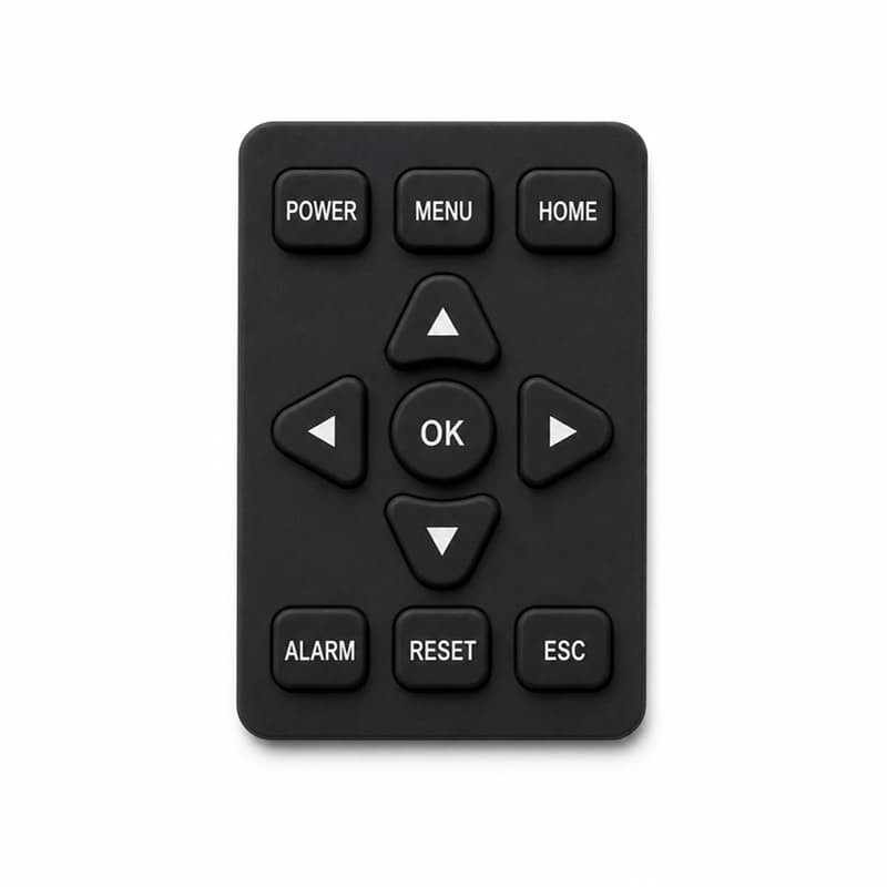
Integration is where most field-instrument keypad problems actually live. The housing geometry defines the opening the pad fills and the wall that traps the skirt. Locating features — alignment holes, molded ribs or a lip — keep the pad in position during assembly; the keypad design guides note that alignment holes are typically needed once the overall pad exceeds roughly 75 mm in either direction [3]. The sealing interface is the compressed contact between the skirt and the housing, and the compression has to be specified as a dimension, not left to chance.
The pad, the opening and the board
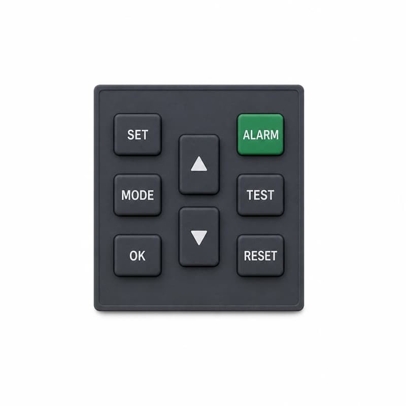
Integration starts with three geometries that have to agree: the housing opening, the pad's outer profile and the PCB contact pattern. When all three are checked together in the DFM review, the first assembly trial is a confirmation; when they are checked separately, it is an investigation.
Compression, tolerance stack and button alignment are the three checks we run on any assembled instrument. The pad is the flexible member that absorbs the stack-up of the housing and the PCB; if the drawing sets it to nominal dimensions only, the assembled unit will show keys that work in one corner and not the other. The assembly process matters too: a pad that is easy to mis-seat during production will be mis-seated, so the locating features have to make correct seating the natural outcome of the assembly step.
How Can a Silicone Keypad Manufacturer Improve the Reliability of the Electrical Interface?
The electrical interface on a rebar scanner keypad is the conductive carbon pill pressing onto PCB contact pads. Reliability is engineered through four parameters. First, conductive carbon pill design: pill diameter, height and carbon loading set the contact area and resistance. Second, contact area and PCB pad compatibility: the pad geometry on the board has to match the pill footprint, including the gap the pill bridges. Third, contact resistance and compression: the travel budget has to compress the pill firmly onto the pads across the full assembly tolerance, not just at nominal. Fourth, alignment and electrical inspection: every key is tested for continuity and contact resistance at rated force on a sample basis, because a pill that lands off-center is the classic intermittent-contact failure.
The keypad manufacturer's design guides document the electrical property ranges of silicone keypad contacts — contact resistance values in the low hundreds of ohms for conductive contacts, insulation resistance above 100 MΩ at 250 V, and contact bounce below roughly 12 ms [4]. Those ranges are design targets; the instrument's actual switching circuit defines what is required. What matters for the scanner is that the switch closes reliably, every time, for the life of the instrument — which is a geometry, alignment and testing problem, not a materials marketing question.
How Can a Silicone Keypad Manufacturer Develop a Custom Rebar Scanner Keypad?
A custom rebar scanner keypad develops through a fixed sequence, because each step feeds the next:
- Step 1 — Requirements. Key count, functions, force and travel targets, environmental exposure, graphics, volume.
- Step 2 — CAD/DFM review. Check the housing and PCB data against the pad design before any tooling commitment.
- Step 3 — Prototype. Mold samples from prototype tooling or rapid molds; fit them in the real housing.
- Step 4 — Functional testing. Force-travel curves per key, electrical continuity, sealing fit, tactile review by the OEM's operators.
- Step 5 — Tooling. Production mold design with shrinkage compensation for the chosen compound.
- Step 6 — Pilot run. Sample across cavities and batches; measure force spread and electrical performance.
- Step 7 — Mass production. In-process control of molding parameters, curing and printing.
- Step 8 — Quality control. Dimensional sampling, force and resistance checks, graphics inspection, batch release.
The sequence looks long because it is: a field-instrument keypad is a small part with a long dependency chain. Skipping a step — especially the DFM review — moves the cost and the risk into tooling, where they multiply.
What Should Rebar Scanner OEMs Provide to a Silicone Keypad Manufacturer?
A detailed starting package for a rebar scanner keypad project contains:
- Product information — application and operating environment, number of keys and each key's function.
- Mechanical — housing CAD, PCB CAD, and mounting or locating requirements for the pad.
- Functional — target force, target travel, and the desired tactile response (snap ratio).
- Electrical — contact pad layout, conductive pill requirements, and any circuit constraints.
- Cosmetic — colors, logos, symbols, surface finish, and any backlit areas.
- Production — annual volume, packaging requirements, and inspection expectations.
OEMs that send this package in the first inquiry consistently get quotes with fewer assumptions and prototypes that fit on the first try. Missing data should be flagged as an open item, not silently guessed.
Common Keypad Design Problems in Field Inspection Equipment
The recurring problems in field inspection equipment keypads are consistent enough to list:
- Key force is inconsistent — keys on the same pad feel different because each key area has its own web geometry but one force target.
- Buttons are too close — gloved fingers hit neighbors; spacing was set for bare-finger use.
- Tactile feedback is unclear — the snap ratio is too low, so the operator cannot tell whether the press registered.
- Conductive contacts are unreliable — pill alignment or overtravel fails once housing and PCB tolerances stack up.
- Keypad does not fit the housing consistently — no locating features, or the pad was drawn at nominal dimensions only.
- Graphics wear prematurely — legend ink that cannot survive site gloves and cleaning.
- Flash interferes with assembly — molding flash at the skirt edge prevents clean seating.
- Prototype geometry is unsuitable for mass production — the web or pill geometry is not repeatable across cavities and batches.
Each of these is a drawing-stage decision, which is why the DFM review comes before tooling — not after.
How Does a Silicone Keypad Manufacturer Support NDT Equipment OEMs?
The support an NDT OEM needs goes beyond molding parts. It covers DFM review of the interface, material selection matched to the field environment, mold engineering with shrinkage and cavity control, prototype development that fits and seals in the real housing, force tuning to a measured curve, conductive contact engineering aligned to the PCB, production QC with documented batch release, and engineering change management when the instrument design moves. A silicone keypad manufacturer works as an engineering partner on the instrument interface — because for a field scanner, the keypad is part of the complete instrument interface, not an isolated molded rubber component.
FAQ
What makes silicone keypads suitable for rebar scanners?
A silicone keypad is molded as one continuous part, so it can seal the instrument front, carry the button layout and provide tactile feedback in a single component — suited to a portable field instrument that must keep dust and moisture away from the PCB.
How are silicone keypad buttons designed for field equipment?
Button size, spacing, web geometry, actuation force and surface texture are set from the operating requirements: gloved use, repeated pressing, temperature range and the need for eyes-off tactile recognition.
Can a rebar scanner keypad be customized?
Yes. Key layout, force, travel, surface finish, graphics, conductive contacts and the sealing interface are all moldable design parameters, developed against the scanner's housing and PCB data.
How is tactile feedback controlled?
Through the force-travel curve: the actuation force where the web collapses, the contact force where the pill touches the PCB, and the snap ratio between them [3]. The curve is set by web geometry and compound, then verified with a load-cell tester.
How are conductive carbon pills tested?
Per key: continuity, contact resistance at rated force, and switch reliability over repeated cycles. The design guides document typical electrical property ranges of silicone keypad contacts [4].
Can silicone keypads be integrated with waterproof housings?
Yes. The continuous membrane of the pad is itself the sealing element, and the skirt is compressed against the housing. For fully sealed assemblies, the keypad design rules specify venting paths between keys rather than guide holes to the outer edge [4].
Conclusion
A silicone keypad for rebar scanner applications should be developed as part of the complete instrument interface — not as an isolated molded rubber component. The documented TMRS-710 shows a portable scanner operated through a silicone keypad across a −10 °C to +42 °C working range [1][2]; the engineering underneath — tactile feedback, non-slip and durable surfaces, reliable conductive contacts, sealing and locating design, and cavity-level production control — is where a custom silicone keypad manufacturer earns its place. If you are developing a concrete inspection scanner, a 3D housing, PCB layout and a button plan are usually enough for a silicone rubber keypad manufacturer to begin a DFM review.
This article was written by the molding engineering team at FromRubber, a custom silicone keypad manufacturer in Dongguan, China. We mold instrument keypads for portable NDT and field inspection equipment, and the checks described here are the ones we run on our own shop floor before a pad is released to production.
Related reading
Sources
- [1] TMTeck Instrument Co., Ltd, "TMTECK TMRS-710 Integrated Rebar Detector Scanner" (Operation: Silicone keypad). https://www.tmteck-instruments.com/tmteck-tmrs-710-integrated-rebar-detector-scanner-product/
- [2] TMTeck Instrument Co., Ltd, "Integrated Portable Borderless Rebar Detector In Concrete TMRS-710" — specifications. https://m.tmteck-ndt.com/sale-36715204-integrated-rebar-detector-portable-rebar-detector-tmrs-710.html
- [3] Diamond HMI Ltd, "Rubber Keypad Design Guide". https://www.diamondhmi.co.uk/wp-content/uploads/2020/02/Diamond-HMI-Rubber-Keypad-Design-Guide.pdf
- [4] KPB Service, "Electrical Properties and Design Rules for Silicone Rubber Keypads". https://kpb-service.com/wp-content/uploads/2018/05/Rubber-Keypads.pdf
- [5] ASTM International, "Standard Test Method for Rubber Property — Durometer Hardness", ASTM D2240-15(2021). https://www.astm.org/d2240-15r21.html