Silicone Thin-Film Switch vs. Traditional PCB: A Flexibility Comparison
- Share
- publisher
- Suey
- Issue Time
- Jul 28,2025
Summary
Silicone thin-film switch versus a traditional PCB compared on fatigue rather than strength: bend radius, conductor resistance, connector strategy, cost at low volume, and the design rules that stop a flexible switch failing in the field.
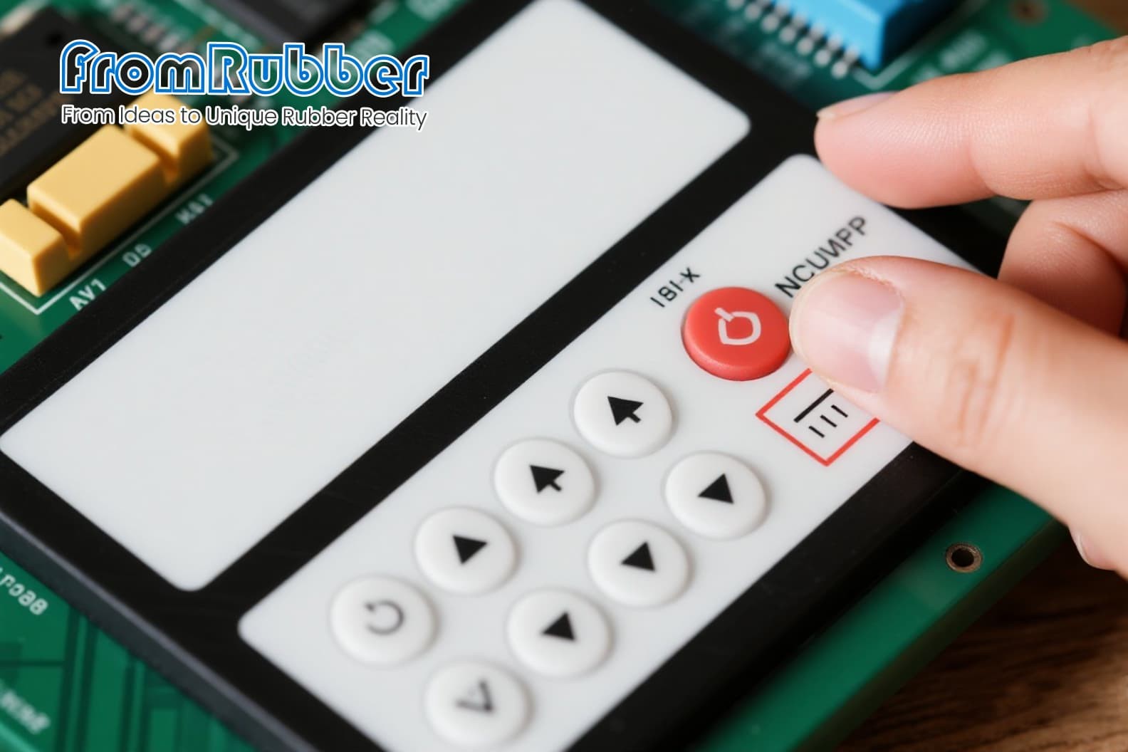
A rigid PCB breaks when the product bends. A thin-film switch bends because that is what it is designed to do. The comparison is not about which is more advanced; it is about how much movement the assembly will see.
This compares a silicone thin-film switch with a conventional PCB on the criteria that decide the choice: fatigue, curvature, connector strategy and cost at low volume.

Silicone Thin-Film Switch vs Traditional PCB: Which Fits a Flexible Product?
The direct answer: if the circuit must bend, twist or follow a curved surface in use, a thin-film construction is the only one that survives. If the board is fixed and the volume is high, a PCB is cheaper and better understood by every assembler in the supply chain.
The distinction is fatigue, not strength. A PCB fails suddenly at a crack. A thin-film circuit on a flexible substrate tolerates repeated bending within a defined radius, and fails by resistance drift rather than by breaking.
The Comparison That Matters
The resistance row is the trade. Printed conductors carry less current and show more variation, so a thin-film design must budget for it from the start rather than discovering it at validation.
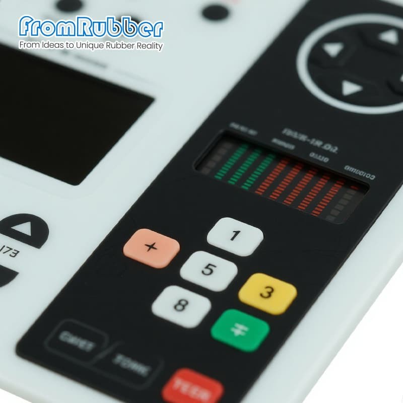
| Criterion | Thin-film switch | Traditional PCB |
|---|---|---|
| Bending in use | Designed for it, within a minimum radius | Not tolerated; cracks propagate |
| Fatigue life | High at moderate bend radii | Effectively zero once flexed |
| Conductor resistance | Higher; printed inks are less conductive | Low and stable |
| Connector strategy | Integral tail to a ZIF or crimp | Header, connector or soldered wires |
| Assembly | Adhesive or mechanical retention | Screws or standoffs |
| Cost at low volume | Artwork-driven, no drilling | Tooling and setup per design |
| Repairability | Replace the panel | Component-level rework possible |
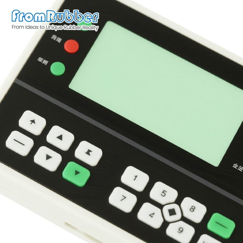
Where a Thin-Film Switch Is the Right Answer
Three cases. The panel follows a curved housing, so the circuit must curve with it. The product is wearable or hand-held and flexes in normal use. Or the switch sits in a membrane stack where a rigid board would add thickness and a connector would add a failure point.
A fourth case is less obvious: low-volume products with complex key layouts, where printed artwork replaces a drilled board and the setup cost is lower than a PCB tooling cycle.
Where a PCB Still Wins
Anything with real current, tight impedance control, or a need for component-level rework. A thin-film circuit is a switch, not a general-purpose board; if the design needs drivers, memory or regulated power, the board stays rigid and the switch stays separate.
Design Rules for a Thin-Film Switch That Lasts
Keep the bend radius generous and never crease the tail at a right angle; a sharp fold concentrates fatigue exactly where the conductors are thinnest. Route conductors away from the fold line where possible, and widen them where they must cross it. Keep the tail short enough to avoid a loop that can catch during assembly.
Specify the bend axis and the expected number of cycles in the drawing, so the construction can be chosen for it. A thin-film switch designed for a static installation and used in a flexing one will pass first article and fail in the field, and the failure will look like a random electrical fault rather than a mechanical one.
Where the switch sits behind a moulded keypad, the two constructions have to be reviewed together; our comparison of silicone keypads and membrane switches covers that interface, and the assembly options are shown on the membrane switch keypad page.
Frequently Asked Questions
Can a thin-film switch carry power as well as signals?
Limited power, yes, but printed conductors have higher resistance and less margin. Anything that draws real current belongs on a rigid board with proper copper.
How many bend cycles can a thin-film switch survive?
It depends on the radius and the conductor design rather than on a universal figure. Specify the radius and the cycle count you need, then test that combination rather than quoting a number.
Is a thin-film switch repairable?
Rarely at component level. The practical service model is to replace the panel, which is why the tail and connector design should allow replacement without cutting into the product.