Tear Strength Deficiency in Ultra-Thin Hearing Aid Silicone Keypads: Anti-Tear Formulation and Mold Design at 0.2 mm Wall Thickness
- Share
- publisher
- FromRubber
- Issue Time
- Oct 6,2026
Summary
At a 0.2 mm wall section a 0.03 mm deviation is a 15 percent thickness change, and demolding becomes the dominant load case. This article locates where tearing actually starts, explains why tensile strength does not predict tear behaviour, and sets out the geometry, mold, material and process actions that improve thin-section durability, with a validation set for prototype approval.
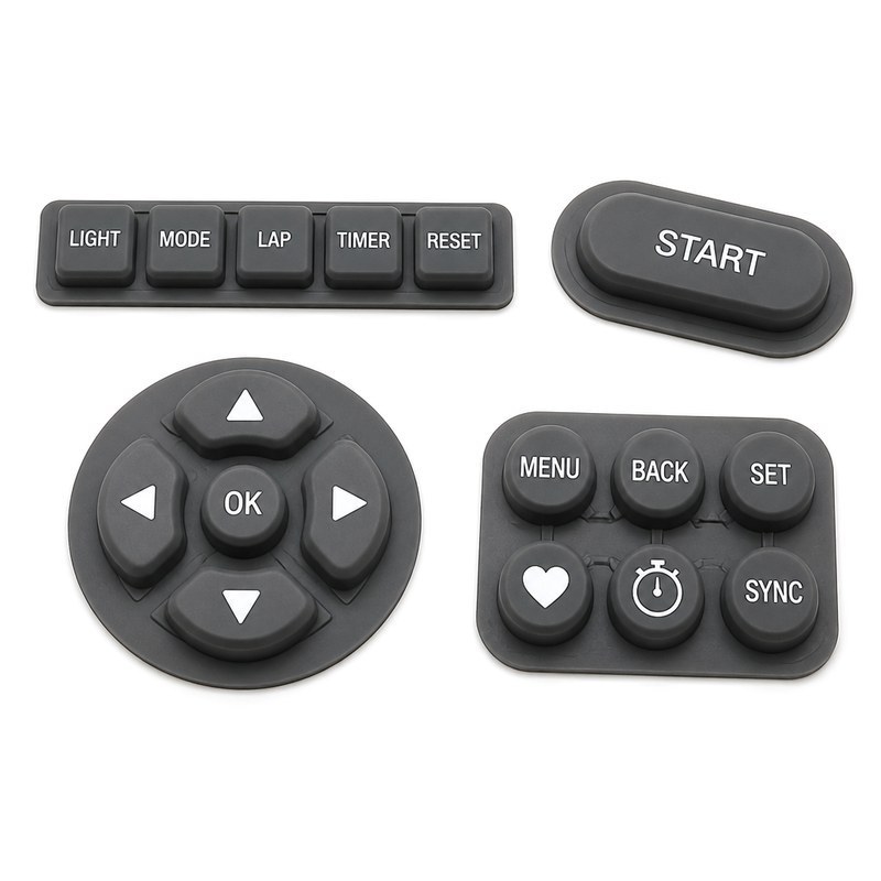
The sample came out of the tool perfectly. Then it tore during trim, and again at the second assembly trial, and the third time at the point where the button web meets the outer flange. The material datasheet says the tear strength is comfortable. That is the moment to stop reading the datasheet, because at 0.2 mm wall section the governing variable is usually not the compound at all.
Why 0.2 mm Silicone Keypad Sections Are Difficult to Manufacture
Thin sections fail the intuition of a drawing. Halving a wall thickness does not simply halve the material, it changes what the part is sensitive to. A 0.2 mm section is affected by cavity depth tolerance that would be irrelevant at 0.8 mm, it sees higher stress at demoulding for the same tool movement, and it has almost no margin before a stress raiser becomes a tear.
Four practical consequences follow. Dimensional variation matters far more, because a 0.03 mm deviation is a 15 percent change in wall thickness. Demoulding stress becomes the dominant load case rather than an afterthought. Tear margin collapses, so a defect that would merely lower a flat specimen's value becomes a functional failure. And the part becomes dependent on the condition of the mould in a way that a standard keypad never is.
The right framing is that 0.2 mm is a different design and manufacturing problem, not a smaller version of a conventional keypad.
A wearable keypad is an assembly, not a part
On body-worn devices the silicone keypad is usually the sealing element, the tactile element and the cosmetic surface at the same time. That means it has to survive demoulding, fixture handling, ultrasonic or adhesive assembly, and then a life of small-radius flexing against a housing edge. Each of those steps loads the same thin section.
Where Tearing Usually Starts in Ultra-Thin Silicone Keypads
Sharp Geometry Transitions
Any transition from a thicker region to a 0.2 mm region is a stress concentrator. A step change in thickness is worse than a gradual taper, because the load has to cross a discontinuity rather than being distributed along a slope. The fix is geometry, not material.
Corners and Small Radii
Below a certain radius the mould simply cannot reproduce a full fillet, so the part arrives with a sharper corner than the drawing shows. If the intended radius is 0.1 mm and the tool leaves a near-sharp edge, the local stress rises by a factor that no formulation change will recover.
Button-to-Web Junctions
Where a raised button meets the thin web, three things coincide: a thickness change, a flow-front meeting point in the mould, and the location of maximum bending during actuation. This is the most common origin of a tear that only appears after a few thousand presses.
Ejecting and Demolding Areas
Ejector pins push on the part while it is still hot and still partly adhered to the cavity. On a thin section, the local stress under a pin can exceed the tear strength even when the average stress in the part is low. Ejector placement matters as much as ejector force.
Local Thin Spots
A cavity that is 0.17 mm deep where it should be 0.20 mm produces a part that looks correct and fails early. Thin spots are invisible on a finished black part and obvious on a cross-section, which is why first-article inspection on ultra-thin work should include a sectioned sample.
Flash or Parting-Line Defects
Flash at a thin edge acts as a crack starter. When the flash is trimmed, the cut can leave a nick that propagates at the first flex.
How Silicone Formulation Affects Tear Strength
The Relationship Between Hardness and Tear Resistance
Hardness and tear strength are correlated in a general way and decoupled in detail. Increasing hardness will often raise tear resistance up to a point, then the material becomes less able to redistribute local stress and the benefit stops or reverses. Using a harder compound to solve a tear problem is a common first move and a frequent dead end.
Tensile Strength Versus Tear Strength
These are different properties and they do not move together. Tensile strength describes how much stress a specimen carries before breaking when pulled uniformly. Tear strength describes the resistance to a propagating cut or nick under a deliberately localised stress. A compound can have excellent tensile values and modest tear values, because the tensile test never introduces a stress raiser.
Elongation and Flexibility
Thin sections need elongation and recovery because they are working in bending, not in tension. A material that elongates well distributes bending strain over a longer region, which lowers the peak strain at the junction. Low elongation compounds fail at junctions even with high hardness.
Filler and Reinforcement Effects
Filler type, loading and surface treatment all influence tear behaviour, and they interact with cure. The honest position is that reinforcement improves tear resistance within a window, and outside that window it makes the material more brittle. There is no single additive that solves a thin-section tear problem.
Read the thin wall, not the datasheet
A tear that starts at a 0.2 mm junction is a measurement problem before it is a material problem. Sectioning one sample and measuring the wall at the junction, at the transition and at the flange tells you which of the three is actually thin, and that single measurement usually decides whether the next action is a formulation change or a tool change.
How Mold Design Influences a 0.2 mm Silicone Keypad
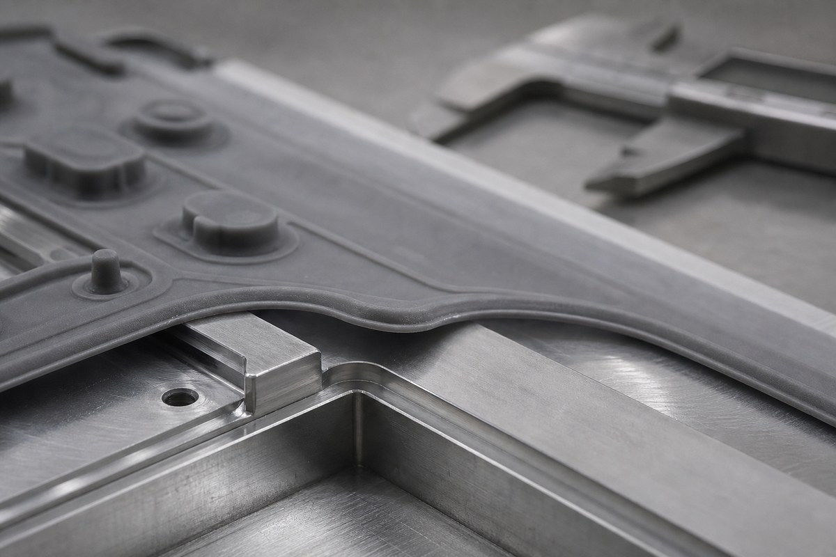
The mould is where most ultra-thin problems are either created or prevented. The parameters that matter are cavity thickness consistency, the form of the transitions, radii, venting, parting line position, mould surface condition, demoulding direction, undercuts and ejection stress.
Venting deserves particular attention. Air trapped in a 0.2 mm cavity has nowhere to go and no time to leave. The result is a short shot, a thin spot or a surface defect, all of which become tear origins. Parting line position matters for the same reason it does on a thick part, only more: a parting line crossing a thin edge produces flash that has to be trimmed, and trimming a thin edge is how a nick gets introduced.
Why Demolding Can Tear a Silicone Keypad Even When Material Tear Strength Is Acceptable
Demoulding failures are frequently reported as "the material tore", which misdirects the investigation. The real causes are usually these:
- Adhesion to the mould surface, often from release agent inconsistency or cavity contamination
- Undercut geometry that requires the part to stretch over a feature to release
- Insufficient draft, so the part drags against the cavity wall
- Uneven cooling or curing, leaving part of the section weaker than the rest at the moment of ejection
- Excessive ejection force applied through a small pin area
- Thin-section deformation during manual handling before the part has cooled
Notice that five of the six are process or tool conditions. This is why we treat a demoulding tear as a tooling conversation first.
How to Improve Tear Resistance in an Ultra-Thin Silicone Keypad
The work divides into four areas, and they should be addressed in this order.
| Area | Actions | What it addresses |
|---|---|---|
| Geometry | Larger radii, tapered thickness transitions, reinforced junctions, removal of unnecessary sharp corners | Stress concentration at the origin point |
| Mould | Controlled cavity depth, correct venting, suitable surface finish, controlled parting line, ejector placement | Thin spots, flash nicks, ejection damage |
| Material | Appropriate silicone grade, defined tear and elongation requirements, hardness chosen for the geometry | Available strain before failure |
| Process | Consistent moulding parameters, controlled cure, careful demoulding routine | Part-to-part variation and handling damage |
How to Test a 0.2 mm Silicone Keypad Before Mass Production
A validation set for thin-section work should combine material testing and part testing. Tear strength and tensile testing of the compound establish the material baseline; repeated pressing, flexing, and a demoulding simulation establish whether the geometry and the process can deliver that baseline in a real part. A simulated assembly step is worth including, because the handling load during assembly is often higher than the operating load in service.
| Test | What it tells you | When to run it |
|---|---|---|
| Tear strength on the compound | Material baseline, comparable between batches | Incoming and per compound lot |
| Tensile strength and elongation | Strain capacity available for bending | Incoming and per compound lot |
| Sectioned wall measurement | Whether the mould is producing the intended thickness | First article and after tool service |
| Repeated pressing | Junction fatigue behaviour | Prototype and pre-production |
| Flex and demoulding simulation | Whether the part survives the process, not just the user | Prototype |
| Assembly trial | Handling and fixture loads | Pre-production |
Hearing Aid Keypad Design Considerations Beyond Tear Strength
Tear resistance is necessary but not sufficient. A hearing aid keypad also has to deliver a defined tactile force, a defined travel, a compact geometry that fits the available face area, a dimensional tolerance tight enough for the housing, resistance to environmental exposure including perspiration, suitability for skin contact, an appropriate surface finish, and an assembly interface that does not pre-load the thin section.
Tactile force and tear resistance often pull in opposite directions: the softer, more compliant geometry that gives a pleasant press is also the geometry that concentrates bending strain. Resolving that trade-off is the actual engineering task, and it is normally settled by geometry rather than by compound choice.
Thin-section work belongs to the same custom silicone rubber keypad family as conventional keypads; what changes is the tooling and the inspection routine. The interface details we need before reviewing a geometry are listed under technical support.
What we ask for on a thin-section enquiry
For a 0.2 mm project, the useful inputs are the housing interface drawing, the required tactile force and travel, the number of keys and their relative positions, and the smallest radius the design actually needs. When a customer has no 3D data and only a sample of the housing, that is still workable: we can measure the interface and work back to a moulding model.
FAQ
Can silicone be molded at 0.2 mm thickness?
Yes, and it is regularly produced, but it needs tooling built specifically for thin sections, tight cavity-depth control and a demoulding routine designed around the part. It is a different process window, not a tighter setting on a standard one.
Why does thin silicone tear during demolding?
Usually because of adhesion, undercut geometry, insufficient draft or an ejection point that concentrates force, rather than because the compound lacks tear strength. Comparing a sectioned sample against the tool drawing is the fastest way to find out which.
Does softer silicone always have lower tear strength?
No. The relationship is not monotonic and it depends on the filler system and cure. Softer grades can perform well where the failure mode is bending, because the strain is distributed over a larger region instead of concentrating at one junction.
How can mold design improve thin silicone keypad durability?
By removing stress raisers that the material cannot compensate for: tapered rather than stepped thickness transitions, controlled cavity depth, correct venting to prevent thin spots, ejector placement that spreads the load, and a parting line that avoids creating a trimming nick on a thin edge.
What is more important for thin silicone, tensile strength or tear strength?
They answer different questions, so a thin-section project needs both. Tensile strength and elongation describe how the section behaves in bending; tear strength describes how it behaves once a defect or a nick is present. A part with good tensile values and poor tear resistance will still fail at the trim line.
How should a 0.2 mm silicone keypad be tested?
Start with compound-level tear and tensile data, then add part-level tests that reproduce the real load cases: sectioned wall measurement, repeated pressing, flexing, a demoulding simulation and an assembly trial. Part-level results are the ones that predict whether the part ships.
FromRubber is a silicone keypad manufacturer in Dongguan, China, working on thin-section and thin-wall keypad projects where geometry, tooling and formulation have to be settled together. If you are developing a small-format keypad with a difficult wall thickness, send the interface drawing or a housing sample and the tactile requirement to nani@fromrubber.com or karl@fromrubber.com, or reach us on WeChat and WhatsApp at +86 18676210913. Related design and moulding notes are collected in our silicone keypad technology articles.
Sources
- ISO 34-1:2022, Rubber, vulcanized or thermoplastic — Determination of tear strength — Part 1: Trouser, angle and crescent test pieces. https://www.iso.org/standard/82445.html
- ISO 48-4:2018, Rubber, vulcanized or thermoplastic — Determination of hardness — Part 4: Indentation hardness by durometer method (Shore hardness). https://www.iso.org/standard/74969.html
- ISO 188:2023, Rubber, vulcanized or thermoplastic — Accelerated ageing and heat resistance tests. https://www.iso.org/standard/80468.html