Top 10 Design Features to Look for in Radar System Enclosures for Real-Time Display Monitoring
- Share
- publisher
- Suey
- Issue Time
- Apr 27,2026
Summary
A radar system enclosure is an electrical component, not a box. Window thickness tunes the passband, seam continuity decides EMI leakage, and wall and coating choices decide whether the display stays in specification when the sun hits it. Ten design features, ranked by failure impact, with the check that proves each one.

Design feature review
A radar system enclosure changes the signal it protects. The window is a dielectric layer whose thickness and flatness shift phase and beam pattern, the seam is an aperture that leaks above a predictable frequency, and the wall is a thermal path for the RF board. Treat the enclosure as part of the RF and thermal design and ten features become checkable requirements rather than preferences.
- Window thickness tolerance and flatness belong in the same specification as the beam pattern, not in a cosmetic drawing tolerance.
- EMI continuity is a seam problem: gasket compression, coating coverage and fastener pitch decide it.
- Ingress and thermal performance are proven on the assembled unit, never on the bare housing.
What a radar system enclosure must do that a generic housing cannot
A generic instrument housing protects a board from dust and impact. A radar enclosure also has to be electrically transparent in one direction and opaque in another, mechanically flat to a fraction of a millimetre, and thermally conductive where the RF front end sits.
The window is the hardest part. Its thickness is chosen as a multiple of the guided wavelength at the centre frequency, and a moulding tolerance of ±0.1 mm on a 2.4 mm window is a phase error the radar has to absorb. Flatness matters as much: a dished window behaves like a lens and distorts the beam, which shows up as angular error in the display rather than as a housing defect.
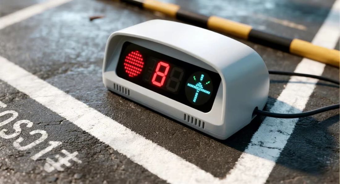
The ten features, ranked by what happens when they are missed
The order below follows failure impact, not cost. The first four cause a functional or certification failure; the remainder cause reliability and user-experience problems that surface after installation.
- RF window dielectric thickness and tolerance — sets insertion phase and return loss; specify a nominal wall with a two-sided tolerance and measure it in the cavity.
- Window flatness — beam distortion appears as angular error; hold flatness to a fraction of a millimetre across the aperture.
- Seam and gasket EMI continuity — slots longer than about one twentieth of the wavelength leak; control gasket compression and fastener pitch.
- Conductive coating adhesion and continuity — a coating that flakes at the seam is an open slot; test surface resistance and cross-hatch adhesion.
- Thermal path from the RF board — pad, gap filler or heat spreader must reach the housing wall; verify by thermal imaging under soak.
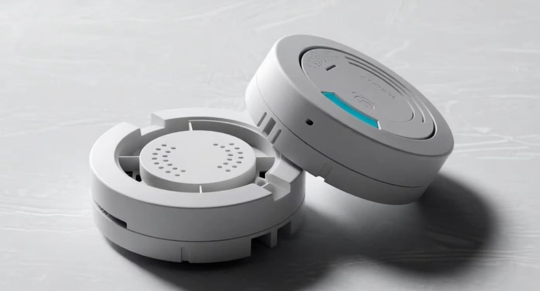
The remaining five features and how each one is verified
These are the features that separate a unit that survives commissioning from one that returns in the second year.
| Feature | Why it matters | How to verify |
|---|---|---|
| IP67 sealing at the cable entry | Water follows a cable into an upward-facing gland | Immersion and dust test on the fully assembled unit, including the harness |
| Display window optical quality | Haze and distortion make the read-out ambiguous at distance | Haze and transmission measurement on production parts, not a first-off |
| Mounting datum and tilt adjustment | Boresight error is set by the bracket, not corrected in software | Angular check against the datum with a fixture, reported in degrees |
| UV and colour stability | Yellowing changes appearance and solar load on the same face | Accelerated weathering to an agreed hour count, with colour difference reported |
| Assembly and service access | A housing that needs a special tool slows every maintenance visit | Time a service opening with the production tooling, not with a prototype |
Three enclosure decisions that cannot be reversed after tooling
Window material and wall thickness
Once the cavity is cut, the dielectric thickness is fixed. Confirm the material grade, its dielectric constant across batches, and the thickness window against the radar specification before release.
Coating process route
Spray coating, conductive filler in the resin and secondary metallisation each need different surface preparation and different gate positions. Choosing late forces a tool change.
Gasket groove geometry
Groove depth and width set the compression percentage. A groove cut for a 2.0 mm cord cannot be rescued by a 2.5 mm gasket without over-compressing it.
Ingress and thermal performance are proven on the assembled unit
A bare housing that holds IP67 tells you the moulding is sound; it does not tell you the product is sealed. Once the harness, the grommet and the connector are fitted, the pressure boundary moves to the cable entry, and that is where most commissioning failures appear.
Test in the order the product lives: thermal soak, then vibration, then immersion. Vibration after a heat cycle relaxes gasket compression, so an immersion test run first flatters the design. Report the sequence in the validation plan and keep the same sequence for every design change.
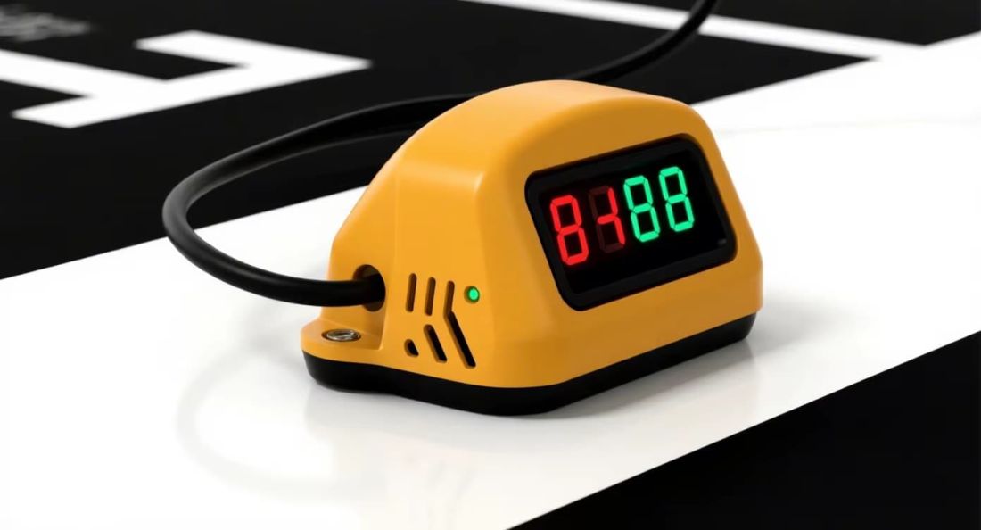
Which design feature actually predicts a radar housing failure
Ten features look equally important on a specification sheet, but field returns rank them differently. Cable entry sealing, lid flatness and UV stability of the front face account for most water-ingress and cosmetic complaints; wall thickness and impact rating rarely decide the outcome, because the housing is mounted out of reach. The list is useful only when it is ordered by failure frequency.
The second predictor is thermal. A radar module in a sealed plastic box runs warmer than the datasheet assumes, and the internal temperature rise shifts the oscillator and shortens the life of the electrolytic capacitors on the board. A housing with a metal heat-spreader pad and a defined contact area costs more per unit and removes a category of warranty claim that no amount of sealing will fix.
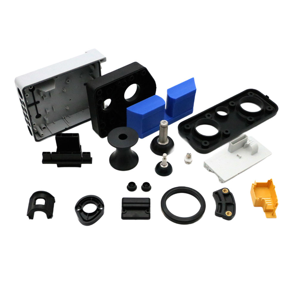
Enclosure questions during radar integration
Does a thicker window improve radar performance?
No. Window thickness is chosen to be electrically neutral at the operating frequency, which usually means a half-wave multiple in the material. A thicker wall simply moves the design to a different multiple and adds loss; the requirement is accuracy and stability, not thickness.
Can EMI shielding be added after moulding?
Conductive paint or metallisation can be applied afterwards, but adhesion, coverage at the seam and masking of the window all have to be designed in. A housing designed without a coating route usually ends up with a seam that cannot be closed reliably.
Why does the display show angular error when the housing looks straight?
Because flatness and thickness of the window, not the visible geometry, set the beam. Measure the window on a granite plate and across its thickness; a dished window of a few tenths of a millimetre is enough to move the reported angle.
Review the enclosure as part of the RF design
Send the enclosure drawing, the operating frequency and the ingress requirement. FromRubber reviews window geometry, seam design and coating route, then returns a DFM report with the tolerances that need to be functional rather than cosmetic — tooling, moulding and secondary operations under one roof in Dongguan.
Request a radar enclosure design reviewRelated reading: cost-benefit analysis for guidance system housings and conductive and decorative coating.