What Causes Silicone Keypad Flash in Mass Production?
- Share
- publisher
- FromRubber
- Issue Time
- Nov 19,2026
Summary
Flash around silicone keypad buttons is rarely a trimming problem. It is a parting-line, preform and tool-temperature problem, and its location tells you which one has drifted. A technical look at mechanisms, mould design levers and what to inspect before approving a custom silicone keypad.
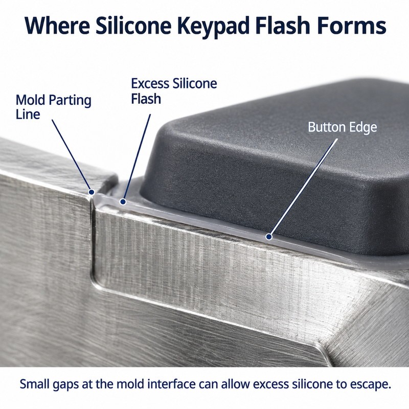
A keypad that leaves the press with a hairline of rubber webbing between forty buttons does not have a trimming problem. It has a tooling and process balance problem, and trimming is only where you notice it.
Flash on a silicone keypad is material that escaped the cavity before the compound had cured enough to stop moving. On a sound tool the amount is small and comes away in a controlled deflash step. On a tool that is marginal, the same compound, the same press and the same operator produce a sheet that takes two people and a sharp knife to clean — and the buttons underneath still measure differently from the first article approved six months earlier.
What follows is not a list of causes in order of importance. It is a way of reading where the material left the cavity, because the location of the flash tells you more about the process than the quantity does.
Why Does Flash Develop Around Silicone Keypad Buttons During Production?
Silicone compression moulding is a displacement process. A weighed preform goes into the cavity, the platens close, and the compound has to fill the shape before the cure takes hold. Nothing confines it except contact between two steel surfaces and the resistance of the material itself. Anything that opens a path at that interface, even by a few micrometres, lets compound out.
The perimeter is longer than it looks. On a typical keypad tool the parting line runs around every button skirt, across the web between keys and along the outer edge of the pad. That is metres of seal on a single part, and every millimetre of it is a candidate.
How Excess Silicone Material Escapes Along the Mold Parting Line
Two conditions have to be true at once: the compound must still be able to flow, and there must be a gap to flow into. In the first seconds of closing, the compound is at its lowest viscosity — warm, unvulcanised and being squeezed. Cavity pressure at that moment is what pushes material sideways.
The escape rate is far more sensitive to gap height than most operators expect. For flow between two flat surfaces, leakage rises roughly with the cube of the gap. Halve the gap and the flow drops by close to eight times. That is why a tool can run clean for a week and then throw flash after the platens heat up and deflect. The gap did not need to change by much.
Flash grooves help, but they cannot rescue a parting line that is not closing. A groove gives escaped material somewhere to collect so it lifts off as one thin film instead of smearing across the button edge. If the gap is the problem, the groove just fills faster.
Why Flash Often Appears Around Individual Buttons and Their Edges
Flash distributed evenly around the whole pad usually points at closing force or preform weight. Flash that appears around some buttons and not others is a different story. It follows the pressure map of the cavity, and that map is not uniform.
On a large keypad the centre of the platen deflects less than the rim. A plate loaded in the middle bows, so the parting line at the outer keys opens first. Button density does the same thing from the other direction: a cluster of keys with narrow webs needs more pressure to fill, and the compound takes the easiest route — outward.
This produces the pattern that is easiest to misread: flash on the outer edge of the pad and none in the middle, or flash on one half only. The instinct is to add preform weight. That makes the middle worse and does nothing for the rim. The pattern is telling you to look at the press and the tool, not the scale.
How Thin Button Walls and Complex Geometries Increase Flash Risk
A button with a thin skirt and a thin connecting web has very little flow area. To fill it, the compound has to be pushed harder, and the harder it is pushed the more it wants to leave through the parting line. Geometry quietly sets the difficulty of the whole job before a single parameter is dialled in.
The same applies to features that are easy to add late in a design review: a second colour shot moulded around a first, a deeper light well for a backlit key, an icon standing a few tenths of a millimetre above the surface. Each one adds a restriction upstream and raises the pressure needed to fill the cavity.
Geometry also decides where the flash lands. A tall button with a steep wall pushes flash to the base of the skirt, where it is almost invisible until the key is assembled and the skirt no longer seats on the dome. A shallow button pushes it onto the top edge, where it shows in the first photograph a customer takes.
Which Manufacturing Factors Make Silicone Keypad Flash Worse?
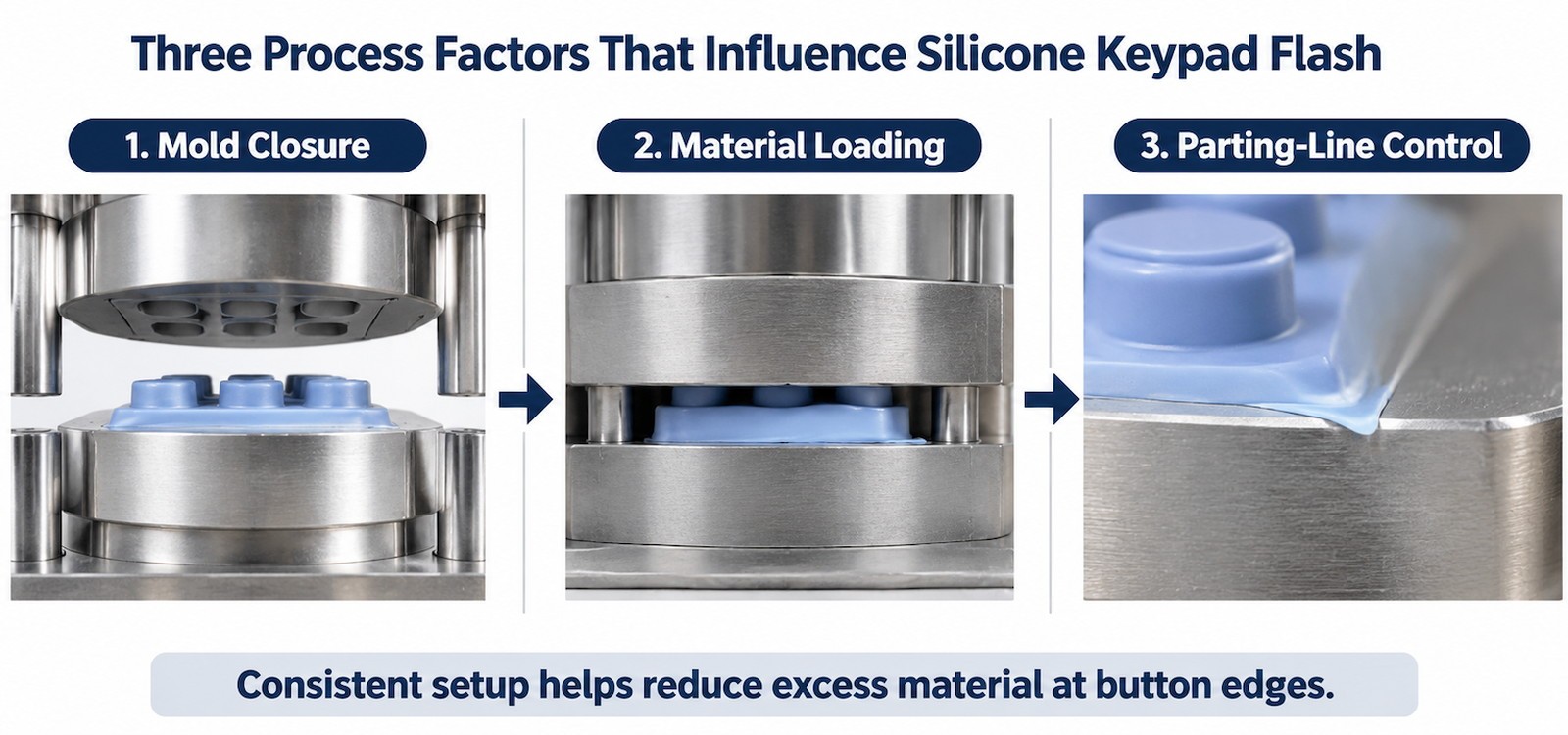
How Mold Clamping Pressure Affects Material Overflow
Closing force and cavity pressure get used as if they were the same number. They are not. The press applies force to the platens; what holds the parting line closed is that force spread over the contact area, minus whatever the frame absorbs.
Hydraulic presses are stiff but not infinitely so, and their platens are not flat under load. The practical difference between a press that closes to a hard stop and one that closes on tonnage shows up in the flash pattern within a single shift. A tool that runs clean on a heavier frame can flash on a lighter one with the same settings — not because the tonnage is lower in the abstract, but because the platen deflects more.
Temperature makes this harder to see. A cold tool at the start of a shift needs more pressure to fill, so the operator raises it. Two hours later the tool is at temperature, the compound flows more easily, and the same setting now overfills the parting line.
Why Incorrect Material Loading Can Lead to Excess Flash
Preform weight is the most common single cause of a step change in flash. The cavity has a volume. If the preform is three per cent heavier than the cavity needs, that three per cent has to go somewhere, and there is only one direction available.
Three loading failures show up again and again. Preforms cut to weight on a scale that drifts. Preforms placed off-centre so one side of the cavity fills first and pushes material across the parting line before the other side closes. Preforms of the wrong shape — one block in the middle of a wide pad has to travel much further than several smaller pieces distributed over the keys.
On multi-cavity tools the error compounds, because the first cavity to fill takes the surplus from the others. Loading discipline is cheap to fix and easy to skip: a weighed preform with a recorded tolerance, a placement fixture and a first-article check at the start of each lot removes most of this variable.
How Curing Conditions Influence Flash Formation and Removal
Cure is a race against flow. The compound must stay soft long enough to fill the cavity, and stiffen soon enough to stop moving. Shift that window either way and the flash changes.
If the tool is too cold or the cure too slow, the compound is still fluid when the press reaches its stop, and it keeps bleeding into the parting line for the rest of the cycle. If the tool is too hot, the surface skins over before the cavity is full, the centre stays soft, and the part can flash when it is ejected and handled. Both look like flash on the inspection bench, and neither is fixed by trimming harder.
Post-cure behaviour is also readable. Flash that comes away soft and stringy usually means the edge was under-cured. Flash that snaps off cleanly but leaves a ragged witness line means the material had cured before it stopped moving. The two point at opposite adjustments, which is why the trimming bench is the wrong place to make the judgement.
| Flash pattern | Likely mechanism | First check | Design or process lever |
|---|---|---|---|
| Even band around all outer keys | Platen deflection under load | Parting-line gap at temperature, not cold | Stiffer frame, smaller cavity area per cycle |
| Only one half of the pad | Mould mismatch or worn guides | Blue-check of the parting surface, guide wear | Re-align halves, replace guide bushes |
| One cavity of many | Preform weight or placement | Weigh preforms per cavity, check seating | Individual preforms, placement fixture |
| Base of tall keys only | Cavity pressure too high for the skirt | Wall thickness against fill pressure | Thicker web, gentler fill path |
| Thin stringy flash after demould | Edge under-cured | Cure log and tool temperature uniformity | Longer cycle, even platen heating |
| Appears after two hours of running | Thermal growth of tool and platen | Gap at start of shift versus mid-shift | Warm-up routine, closed-loop tool temperature |
How Can Mold Design Reduce Flash Around Silicone Keypad Buttons?
Improving Parting Line Accuracy Around Button Profiles
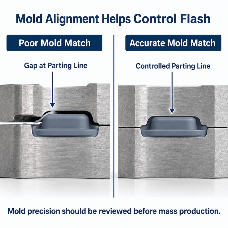
The parting line belongs where the flash is least visible and easiest to remove, and where the two halves can actually be matched. Around a button that usually means the base of the skirt rather than across the top radius. Put it on the radius and you have created a cosmetic edge that cannot be trimmed without changing the button’s silhouette.
Accuracy comes from three things: the parting surfaces machined in the same setup as the cavity, a guide system stiff enough to repeat to a few micrometres, and a tool that is not asked to close on a surface that was polished by hand afterwards. We have seen tools where the cavity was correct and the parting surface had been stoned to remove a mark. The flash followed the stoning pattern exactly.
Before approving a tool, it is worth checking the gap with a feeler gauge at four points around the perimeter, at running temperature rather than on a cold bench. It takes ten minutes and saves weeks.
Adjusting Flash Grooves and Overflow Areas
A flash groove is a controlled place for surplus material to collect. Its depth and its distance from the cavity edge decide whether the flash lifts off as a thin film or tears as a thick bead. Too close and the groove fills and stops working. Too far and the film stretches across the land and pulls the button edge when it is removed.
Overflow areas also vent. Air has to leave the cavity as compound enters it. If the only path out is past the parting line, air and compound travel together, and the result is a short shot next to a flash line — a combination that sends people looking for a material problem that does not exist. A small overflow pocket at the end of the fill gives the air somewhere to go first. More detail on groove placement sits in this guide to parting line design for flash control.
Balancing Button Spacing With Mold Manufacturing Requirements
Designers compress key spacing to fit more functions into a handset-sized window. Every millimetre removed between buttons reduces the width of the steel rib separating the cavities, and a thin rib deflects. It also reduces the land available for the parting line, so the same closing force is carried by less contact area.
There is a workable floor, but it depends on tool steel, cavity depth and the press. A spacing that is comfortable on a single-cavity prototype tool can be marginal on a twelve-cavity production tool where the same rib repeats twelve times and the deflection adds up. This is the point where the keypad layout and the mould layout have to be reviewed together rather than one after the other.
How Should Manufacturers Control Flash During Silicone Keypad Mass Production?
Checking Mold Alignment Before Starting Production
Alignment is a pre-flight check, not a troubleshooting step. Blue-check the parting surface at the start of a run, look at guide-pin and bush wear, and confirm the clamp plates are flat. On tools that have run for years, guide wear is the quiet cause: the halves still close, but they no longer close in the same place, and the flash moves from one side of the pad to the other between lots.
Keeping Material Loading and Molding Conditions Consistent
Consistency beats optimisation here. A recorded preform weight with a tolerance, a placement fixture, a tool-temperature log and a first-article check at each lot start will hold a process that is only average. A brilliant setting that nobody records will drift within a week, because the people running the press change and the tool temperature changes with the weather in the shop.
Inspecting Button Edges and Critical Dimensions After Deflashing
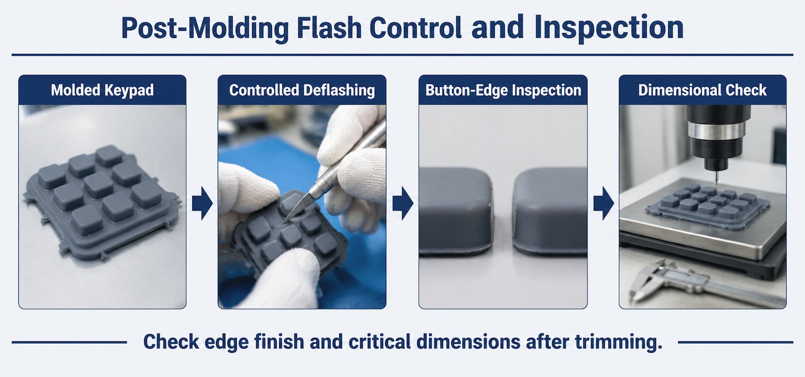
There is a difference between cosmetic flash and functional flash, and inspectors need both definitions. Cosmetic flash sits on a visible surface and affects appearance. Functional flash sits where the skirt seats on a dome, inside a locating groove or on a sealing land. Trim the second type badly and the key either loses travel or gains actuation force, and the failure appears at assembly rather than at goods-in.
Check key height, actuation force and edge condition after trimming, not before. Trimming is a material removal operation; it changes the part. A first-article sheet that measures the moulded part and never the trimmed part is measuring the wrong object.
What Should Buyers Check When Evaluating a Custom Silicone Keypad Manufacturer?
Whether the Manufacturer Can Identify Flash Risks During Mold Design
Ask what they would change about your button spacing before the tool is cut. If the answer is nothing, either the design is unusually generous or nobody has looked. A DFM note that flags a narrow web between keys, a thin skirt or a parting line placed on a visible radius is worth more than a tolerance line in a quotation.
How the Manufacturer Controls Edge Quality Across Production Batches
Batch consistency is a process question, not a trimming question. Ask how preform weight is controlled, whether tool temperature is recorded, and what the first-article check covers. A supplier who trims to hide variation will show clean samples and ship parts that fail assembly six weeks later. The flash control and deflashing process only works when the moulding upstream of it is stable.
Why Sample Approval Should Include More Than Button Appearance
Appearance approval catches the flash you can see. It does not catch flash trimmed back into the skirt, which changes the wall angle and the actuation force, or a knife notch left in the button edge. Put the sample on a flat surface under low-angle light, measure key height and actuation force, and fit it into the housing before signing. Cases where a fraction of a millimetre decides whether an instrument keypad survives a million presses are not unusual; the 0.1 mm tolerance that decides keypad life is a useful reminder of how small the numbers are.
Final Considerations for Reducing Flash in Custom Silicone Keypads
Flash is the visible end of a chain that starts at cavity layout and finishes at the trimming bench. The tools that run cleanest are not the ones with the most aggressive deflashing. They are the ones where the parting line closes, the preform weight is known and the tool temperature is stable for the whole shift.
FromRubber, trading name of Dongguan Bohao Electronic Technology Co., Ltd., has been moulding silicone keypads in Dongguan since 2010, with 32 compression presses across two plants, a CNC tool room and more than 7,000 moulds in storage. That mostly means we have seen the same flash patterns on a lot of different parts, including the ones where the answer turned out to be a worn guide bush rather than a new tool. If you are still at the design stage and want a second opinion on button spacing or parting-line placement before the steel is cut, our engineers can review the drawing and the housing interface. WhatsApp and WeChat: +86 18676210913. The contact page has the other channels.
A note on the limits of this article. The mechanisms described are general to silicone compression moulding. The correct gap, preform tolerance and cure window for your part depend on its geometry, compound and tool, and should come from the tool trial and first-article report rather than from any published figure. Where numbers are needed, they are normally taken from indentation hardness testing to ISO 48-4, compression set to ISO 815 and tensile properties to ISO 37, measured on the compound and again on the moulded part.
Frequently asked questions
Is a small amount of flash on a silicone keypad normal?
Yes, in the sense that no compression-moulded part emerges with a perfectly zero-thickness edge. What matters is where the flash is allowed to sit and how thick it may be. Put both limits on the drawing: flash on cosmetic surfaces, flash on sealing lands and flash inside locating features each need a separate line.
Why did flash appear only after the tool had been running for hours?
Thermal growth is the usual explanation. Tool and platen temperatures rise during the shift, the steel expands, and the parting-line gap changes. If a tool is clean when cold and flashes when hot, the fix is a warm-up routine and a gap check at running temperature, not a heavier preform.
Can flash be removed without leaving a mark on the button edge?
It depends on where it sits. Flash on a flat land can usually be removed cleanly with a controlled method. Flash that has flowed onto a radius or into a skirt wall leaves a witness line wherever it is cut, because material is being removed from a curved surface. Design placement prevents the problem; trimming only manages it.
Does a heavier preform always cause more flash?
Usually, but placement matters as much as weight. A correctly weighed preform dropped to one side of a wide cavity can flash on that side while leaving the far keys short. Both faults in one part is a common and confusing combination.
How should an acceptable flash limit be written into a specification?
Define it by location and by function rather than one global number: maximum thickness on visible surfaces, zero tolerance on sealing and seating surfaces, and a witness line allowed or not allowed at the skirt base. Adding a photograph of an acceptable and a rejected edge removes most of the argument later.