What Causes Structural Problems in Silicone Keypads for Cable Fault Locators?
- Share
- publisher
- FromRubber
- Issue Time
- Nov 16,2026
Summary
A structural review of silicone keypads on cable fault locators: how thin sections, base geometry, hardness and mold detail cause deformation, tearing and fit problems, and which checks belong before tooling and before assembly.
A cable fault locator spends most of its life being carried. It rides in a van, gets set down on gravel, is used in drizzle with muddy gloves, and comes back to the workshop with a keypad that no longer returns cleanly on one key. The electronics usually survive. The silicone is what starts to show the working conditions first.
When a keypad fails structurally, the symptom is rarely dramatic: a key that stays slightly down, a thin web that has begun to tear at one corner, a flange that no longer sits flat, a button that needs a harder press than it did a year ago. Each of those symptoms traces back to a geometry or material decision that was reasonable on paper. This article looks at those decisions for field instruments, and at the checks that catch them before a mold is cut.
In short: most structural failures start at a sharp corner or an unsupported thin wall, not in the compound. Check button height against base diameter, keep wall thickness consistent where the design allows, and confirm that the mold can fill, vent and release the thin sections before tooling is cut.
Which Structural Problems Can Affect Silicone Keypads on Cable Fault Locators?
Silicone keypads are thin-shell parts. The whole component is a membrane that carries local stiffeners in the form of button walls and a perimeter flange. When the shell is loaded, force travels through the thinnest section on its way to the switch, and that section is where the part will eventually show wear.
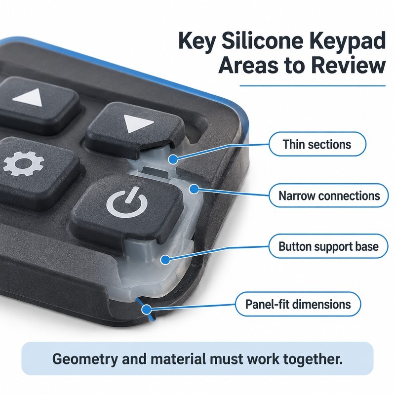
Four problems account for most of the field failures on industrial keypads: excessive deformation in thin sections, unstable button bases, tearing at narrow connections, and dimensional variation that turns assembly into a fight. They are related, because each one changes how load travels through the same shell.
The cutaway above shows where those areas sit in a real part. None of them is a defect on its own. They become problems only when their thickness, radius or support is out of proportion to the load the key sees.
Thin Silicone Sections May Deform During Pressing
A thin web under a button is deliberate: it is what allows the key to travel. The question is how thin, and relative to what. A web that is thin in absolute terms but generous relative to the button wall behaves like a hinge. A web that is thin relative to the button height behaves like a diaphragm, and the whole key sinks and rocks instead of moving straight down.
Field instruments make this worse because they are pressed with the thumb at an angle, not straight down. A membrane that is stable under a perpendicular load can fold under an off-axis one, which is why a key that feels fine on a bench can feel mushy when the instrument is held in one hand and pressed with the other.
Button Bases May Become Unstable When the Supporting Structure Is Poorly Designed
The base of a button is a short cylindrical or conical wall, and it does most of the structural work. If the base diameter is small relative to the button height, the wall has little resistance to sideways load, and the key tilts. A tilted key can rub against the panel opening, which adds friction, and friction is what turns a crisp press into an inconsistent one.
Support does not have to mean a thicker wall everywhere. A short internal rib, a slightly conical profile or a small step at the base often stabilises the key without changing its feel. What matters is that the support is considered as part of the geometry rather than added after a sample feels wrong.
Narrow Connecting Sections May Increase the Risk of Tearing
Between adjacent buttons, the silicone has to remain connected, so the material narrows into a bridge. That bridge carries the same deformation as the surrounding web but over less area, and it usually ends in a corner. A sharp internal corner at the end of a narrow bridge is the single most common starting point for a tear.
The practical fix is geometric rather than material: widen the bridge slightly, add a radius at the transition, and avoid stacking a bridge directly beside a deep recess where the wall is already thin. These changes rarely affect the pressing feel, and they remove the stress concentration that field use will otherwise find.
Dimensional Variations Can Make Keypad Assembly Difficult
A keypad that is 0.2 mm too large around the perimeter will not seat; one that is 0.2 mm too small will not stay located. Both symptoms look like a mold problem and are often an assembly problem, because the panel opening and the keypad flange were toleranced independently without a reference dimension between them.
Locating features matter as much as the outline. Small molded pins, a stepped edge or a shallow groove give the part a defined position instead of relying on friction. On field instruments that are opened for service, a keypad held only by compression is likely to be reinstalled slightly off-center, and the next complaint will be about a sticky button rather than about fit.
How Does Keypad Geometry Affect Structural Stability?
Geometry decides how force is distributed before the material is even chosen. Three relationships cover most of it: button height against base diameter, wall thickness against wall thickness elsewhere on the part, and corner radius against the thickness of the section it joins.
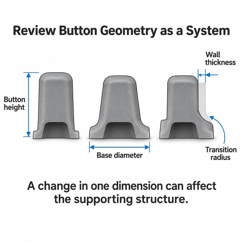
The comparison above is not a recommendation of one profile over another. It shows the three variables that move together: change the height and the base, the wall and the radius all need re-checking, because the part behaves as one system.
Button Height and Base Diameter Should Be Designed Together
Height is usually driven by the panel and by the need to find a key by touch. Base diameter is usually inherited from the key spacing. When those two numbers are set independently, tall keys end up on narrow bases, and the part becomes sensitive to side load. A useful review question is simple: at this height, does the base still look like a support or like a stalk?
Wall Thickness Should Remain Consistent Where the Design Allows
Uniform wall thickness is easier to mold and easier to predict. Where thickness must change, the transition should be gradual. Abrupt changes create two problems at once: uneven curing and shrinkage during molding, and a stress concentration in service. Both show up later as dimensional drift or as a crack that starts exactly at the step.
Sharp Corners and Sudden Thickness Changes Need Special Attention
Silicone is forgiving, but not infinitely so. A sharp internal corner in a thin section concentrates strain, and repeated pressing works that corner until it starts to split. Adding radius is cheap at the drawing stage and expensive after the cavity is cut, which is the reason it is worth reviewing before tooling rather than during sampling.
A useful rule when reviewing a section drawing: mark every point where two surfaces meet at less than a 90 degree internal angle, then ask whether that point will flex during use. Flexing sharp corners are the ones that fail first.
Can Silicone Material Selection Contribute to Keypad Structural Problems?
Material choice cannot rescue bad geometry, but it can amplify it. The same drawing behaves differently in a soft compound and a firm one, and the difference is largest exactly where the part is thin or unsupported.
Silicone Hardness Affects Button Deformation and Pressing Behavior
A softer compound deforms more under the same force. On a key with a generous base, that extra deformation is what gives the key its comfortable feel. On a key with a narrow base, the same softness lets the key rock and makes the press feel vague. Hardness selection therefore has to follow the geometry rather than be set first.
Hardness also changes the force needed to close the switch underneath. A harder key transmits force more directly, which can make a membrane switch feel abrupt, while a softer key absorbs part of the travel. Neither is better in isolation; the pair has to be matched to the intended pressing feel.
Material Flexibility Should Match the Intended Button Structure
Very flexible compounds suit thin webs and low actuation forces; firmer compounds suit tall keys and long travel. Choosing a very flexible material for a tall, narrow key is a common mismatch: the part looks right and feels unstable, because the geometry asks for stiffness the material does not provide.
Material Selection Should Consider the Actual Operating Environment
Field instruments see temperature swings, UV through a vehicle window, oils and solvents from cable work, and cleaning agents. Each of those affects silicone differently, and the effects usually appear as a change in hardness or as surface degradation rather than as a sudden failure. Selecting a compound for the environment is part of structural design, not a purchasing detail.
Where the environment includes solvent contact, it is worth reading how chemical exposure actually behaves on molded keypads before choosing a compound purely on hardness. A note on 40 Shore A versus 60 Shore A hardness selection covers the practical trade-offs between the two common ranges.
How Can Mold Design Influence Silicone Keypad Structural Quality?
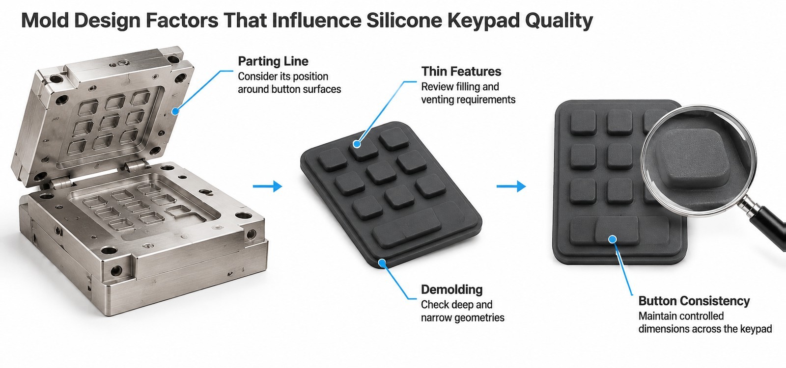
Mold design converts a drawing into a part, and some of the most consequential structural decisions are made there rather than in CAD. Parting line position, venting, demoulding and cavity layout all leave marks on the finished keypad, and some of those marks sit exactly where the part flexes.
Parting Line Placement Can Affect Button Appearance and Function
The parting line is where flash forms and where a small step is unavoidable. Placed across a button's top face, it becomes a visible and tactile artefact that interferes with the very differentiation the design was trying to create. Placed on a sidewall just below the crown, it is usually invisible and has no effect on feel.
Mold Filling and Venting Need to Account for Thin Features
Thin sections are harder to fill and harder to vent. Air trapped at the end of a narrow bridge or in a fine texture produces incomplete filling, which reads as a rounded detail or a weak spot. On a keypad, that weak spot is often in the section that flexes most.
Demolding Can Be More Difficult Around Deep or Narrow Features
Deep cavities and narrow features resist release. If the part has to be stretched or peeled off the core, the geometry that survives demoulding is not necessarily the geometry that was drawn: thin walls can be distorted, and small undercuts can tear. Reviewing release before tooling prevents a design that can be cut but not molded cleanly.
Mold Layout Should Consider Dimensional Consistency Across Multiple Buttons
Cavity layout affects how evenly the compound cures and how consistently the buttons come out. A keypad with eleven buttons needs eleven features that behave alike; if one cavity area runs hotter or fills differently, one key will sit at a different height and the operator will feel it.
What Should Be Checked Before Installing a Silicone Keypad in a Cable Fault Locator?
Incoming inspection tends to focus on cosmetic defects. For a field instrument, the checks that predict reliability are about fit, travel and consistency, and they are quick to run on a sample panel.
Verify the Fit Between the Keypad and the Control Panel
Check the perimeter, the locating features and the flange seat. The keypad should sit flat without being forced, and it should not rock when one corner is pressed. A part that needs pressure to seat is already pre-loaded, and pre-load shows up later as a key that does not return.
Fit problems are often diagnosed as dimension errors when the real cause is the locating design. A note on keypads that feel too tight or too loose in the housing walks through that distinction in more detail.
Check Button Travel and Clearance Around Each Opening
Every button needs clearance inside its panel opening, including at the corners where a molded radius meets a square cut-out. If travel is restricted, the switch may still close but the key will not return fully, and the next press starts from a partly depressed position. That is how a keypad develops a reputation for sticking.
Inspect Thin Sections and Connecting Areas for Visible Defects
Look at the web under each button and at the bridges between features. Incomplete filling, flash across a thin section and local distortion are all visible under a low-angle light. These are the areas that will fail first in service, so they deserve more attention than the top surface.
Evaluate Pressing Consistency Across the Complete Keypad
Press every key in sequence, then press pairs of adjacent keys. Consistency across the panel matters more than the absolute feel of any single key, because the operator learns one panel and notices the outlier immediately.
| Inspection point | What to look for | Why it matters in the field |
|---|---|---|
| Perimeter flange | Flat seat, no rocking, no pre-load | Pre-load leads to keys that stop returning |
| Button travel | Full stroke, free return, clearance at corners | Restricted travel causes sticking and double presses |
| Thin webs and bridges | Complete fill, no flash, no local distortion | These are the first areas to tear |
| Pressing consistency | Even feel across all keys | An outlier key is noticed and distrusted |
How Can Buyers Reduce Structural Risks Before Custom Keypad Production?
Most structural risk is retired with information rather than with money. A drawing with cross-sections, a note about the operating environment and a sample review cover the majority of failure modes described above.
Provide Drawings Showing Critical Dimensions and Cross-Sections
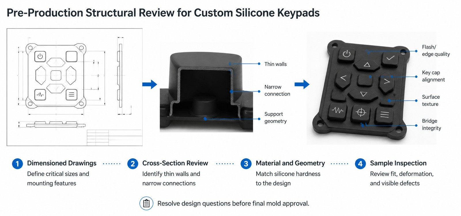
A top view shows the layout; it does not show the web thickness, the wall taper or the radius at a transition. Cross-sections are what a mold maker actually needs in order to judge feasibility, and they are also the fastest way to see whether the part has thin sections in the wrong places.
Marking two or three dimensions as critical is more useful than tightening every tolerance. It tells the supplier where to spend attention during tooling and inspection, and it prevents a good part from being rejected over a dimension that does not affect function.
Identify Areas That Need Additional Structural Review
Thin sections, narrow bridges, deep features and frequently pressed keys are the four candidates. Naming them explicitly in the request turns a general quote into a targeted review, and it gives the supplier permission to propose geometry changes instead of simply quoting what is drawn.
Confirm Material Hardness and Button Feel Through Sample Evaluation
Hardness on a data sheet does not predict feel. A sample pressed by the actual user group in the actual glove answers the question in minutes, and comparing two hardness options on the same geometry is usually worth the extra sample round on a field instrument.
Review Moldability Before Finalizing the Keypad Design
The best time to involve the silicone manufacturer is before the mold design is frozen. Geometry that is hard to fill, hard to vent or hard to release can often be adjusted slightly with no effect on function, but only if the adjustment happens before the cavity is cut.
What Information Should Be Included in a Custom Silicone Keypad Inquiry?
- Cable fault locator model or application, and the conditions the instrument works in.
- Overall keypad dimensions, panel opening and mounting method.
- Button quantity, height, spacing and any differentiating shapes.
- Structural drawings with cross-sections, not only a top view.
- Required silicone hardness, or the pressing feel the design needs.
- Environmental exposure: temperature range, solvents, cleaning agents, UV.
- Surface finish, color and legend requirements.
- Expected production volume and prototype quantity.
- Any known structural concern from an earlier version or a competitor product.
Frequently Asked Questions
Is a torn web always a material problem?
Not usually. Tears start at a stress concentration, which is a geometry issue: a sharp corner, a narrow bridge or an abrupt thickness change. Changing compound can delay the symptom, but the corner will still concentrate strain.
How thin can a silicone web be under a button?
It depends on button size, travel and hardness, so there is no universal figure. The practical limit is set by mold filling and by how much the web has to deform without losing its shape, which is why a sample is the only reliable test.
Why does a keypad that fitted perfectly in the first batch stop fitting later?
Batch-to-batch variation in a thin part is normal, and it becomes visible when the locating design relies on friction. Adding a positive locating feature reduces sensitivity to small dimensional changes.
Does a harder compound make a keypad more durable?
Not automatically. Hardness changes deformation and force, and a harder compound can increase stress at a sharp transition. Durability comes from geometry, transition radii and mold quality as much as from hardness.
Should the parting line be specified on the drawing?
It should at least be discussed. The mold maker will choose a position, and that choice affects both appearance and feel on the button crown, so it is worth agreeing before the cavity is cut.
What causes a key to return slowly after a year of use?
Common causes are pre-loaded assembly, restricted travel in the panel opening, or a web that has taken a permanent set. All three are structural and all three are visible during an incoming inspection on the assembled panel.
Conclusion: Structural Reliability Starts Before Silicone Keypad Molding
Structural problems in a field instrument keypad are rarely caused by one bad decision. They come from a set of small ones: a thin web with no support, a tall key on a narrow base, a sharp corner where the part flexes, a hardness chosen before the geometry, a parting line that landed on the wrong surface. Each is cheap to fix on a drawing and expensive to fix on a mold.
FromRubber reviews keypad drawings for instrument programs, covering button geometry, cross-sections, silicone material selection, mold development, sampling and production. The review is most useful before tooling, when a radius or a wall thickness can still be changed without a new cavity.
Sources and Further Reading
- Custom silicone rubber keypad product range reference constructions for industrial keypads.
- IP67 report pass versus field leakage on industrial instrument keypads sealing behavior in real operating conditions.
- Silicone keypad hardness selection: 40 Shore A versus 60 Shore A practical hardness trade-offs.
- Silicone keymats for instruments and meters reference construction for instrument keypads.
- IEC 60529:1989+AMD1:1999+AMD2:2013 defines the IP code for enclosure protection, which is the reference used when keypad and panel sealing are specified together.
- ISO 13849-1:2023 addresses safety-related parts of control systems and is relevant where a keypad carries stop, reset or mode-selection functions on testing equipment.
Send a keypad section, not just a layout
A top view hides where a keypad will fail. FromRubber reviews cross-sections, wall ratios and mold feasibility for field instruments, and replies with comments before the cavity is cut.
FromRubber is the export brand of Dongguan Bohao Electronic Technology Co., Ltd., Qiaotou, Dongguan, China. IATF 16949:2016 and ISO 9001:2015 certified.