Why Do Silicone Makeup Tools Develop Uneven Edges or Flash After Molding?
- Share
- Issue Time
- Nov 6,2026
Summary
Flash and uneven edges on silicone makeup tools come from a pressure balance between cavity, parting surface and press, not from one defective mould. Covers how flash forms, why edge quality varies between batches, how mould design limits it, and what buyers should confirm before tooling.
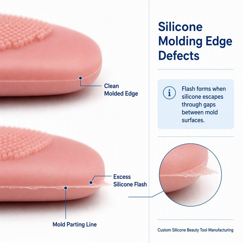
A flash line you can feel with a fingernail will be the first thing a buyer notices, long before they judge the colour or the packaging. On moulded silicone makeup tools, uneven edges and thin flash are rarely a single defect with a single cause. They are the visible result of a pressure balance that failed somewhere between the cavity, the parting surface and the press.
This article looks at where those edges come from, why some batches arrive clean and others do not, and what a buyer can reasonably ask for before a mould is cut. It is written from the production side of custom silicone beauty tools, where the same drawing can produce two very different edge qualities depending on how the tool was built and run.
What Do Uneven Edges and Flash Look Like on Silicone Makeup Tools?
Edge defects on silicone beauty tools fall into a small number of recognisable patterns. Once you can name the pattern, the conversation with a supplier becomes much shorter, because each pattern points to a different part of the process.
How Flash Forms Along the Edges of Molded Silicone Products
Flash is thin, film-like silicone that has travelled past the edge of the cavity and cured outside the intended product outline. On a silicone makeup sponge it appears as a feathered lip running around the widest circumference. On a mask brush or a flexible applicator it usually follows the seam where the two mould halves met. On a small spatula it collects along the blade edge, which is exactly the area a user looks at when they pick the tool up.
The material is not the problem in most cases. Silicone compounds used for compression moulding flow readily under heat and pressure, and they will occupy any gap that offers less resistance than the cavity itself. A parting surface that closes to a few hundredths of a millimetre in one area and opens slightly in another gives the compound a path of least resistance, and the result is a flash line that varies in thickness around a single part.
Two parts from the same mould can look completely different at the edge. The upper example shows a controlled edge where the compound stopped at the cavity boundary. The lower example shows what happens when the same compound finds a gap along the parting line: a translucent film that is soft, difficult to trim cleanly and almost impossible to remove without leaving a witness mark.
That film is also a useful diagnostic. Its location tells you which section of the parting surface is not closing properly, and its thickness tells you roughly how much pressure was lost at that point.
Why Some Silicone Edges Look Rough, Wavy, or Inconsistent
A rough edge and a flashed edge are not the same complaint, even though buyers often use one word for both. Roughness comes from the edge itself: the compound did not fill the last fraction of a millimetre of cavity, or it cured while still moving, or the trim cut into the product outline instead of removing only the excess.
Waviness is a different signal again. A contour that undulates around the perimeter usually means the edge section is thin enough to deform during demoulding. The part is pulled from the cavity while still warm and slightly soft, the thin rim stretches, and the distortion stays once the part cools. On soft silicone applicators with a feathered edge, this can happen even when the mould is accurate.
Inconsistent appearance between parts is the third pattern, and the most commercially damaging. It means the process window is wide enough that ordinary variation in loading, press temperature or operator timing moves the result from acceptable to marginal.
Which Edge Defects Matter Most for Beauty Tool Buyers?
Not every edge is equally important, and treating them as if they were drives cost without improving the product. Three areas deserve priority.
- Skin-contact edges. The rim of a silicone sponge, the tip of a mask brush and the working edge of a spatula are touched directly. A flash film here is felt immediately and can catch on product.
- Handling surfaces. Grip areas and the transition between a handle and a head collect flash that interferes with control during use.
- Batch-to-batch consistency. A slightly visible seam that is identical on every unit is a design characteristic. The same seam appearing on some units and not others reads as poor control, and it is the defect most likely to trigger a claim after delivery.
Where an edge is hidden inside an assembly, behind a lid or under a label, a small amount of controlled flash is a normal and acceptable outcome of a two-plate mould. The engineering judgement is deciding which edges are allowed to show a seam and which are not, and writing that decision into the drawing rather than leaving it to the trimming bench.
What Causes Flash and Uneven Edges During Silicone Molding?
Silicone compression moulding is a process in which a measured charge of uncured silicone compound is placed in an open heated cavity, and the mould is then closed under pressure so the compound fills the cavity and vulcanises. Flash is the material that escapes past the cavity boundary during that closure.
Most flash investigations start with the mould and end there, which is why they often fail. The parting surface is only one of four variables that decide whether compound stays inside the cavity. The other three are how much material was placed in the cavity, how the press brought it to cure, and how the product geometry distributes material as the mould closes.
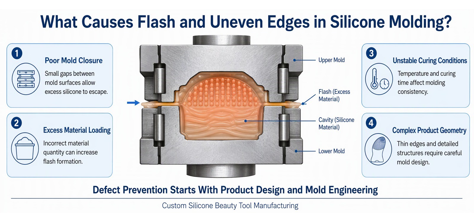
Poor Mold Closure Can Allow Excess Silicone to Escape
Closure is the most direct cause and the easiest to measure. A parting surface that does not seat fully will leak, and it will leak most where the cavity pressure is highest. Common reasons include wear on the locating pins after long production runs, a hardened film of cured compound left on the sealing land, distortion of a thin mould plate under clamp force, and a mismatch between the two halves introduced during finishing.
The consequence is not uniform. A mould that leaks slightly at one corner produces flash only on the parts positioned near that corner, which is why cavity-layout matters when you are reviewing a sample set. If the flash appears on every cavity, the cause is more likely to be material volume or press parameters than a localised closure problem.
Our own experience with multi-cavity silicone tooling follows the same logic described in silicone mould parting line design for flash control, where the sealing land is treated as a functional surface with its own maintenance schedule rather than as an inert face on the mould.
Excessive Material Loading Can Increase Flash Formation
Compression moulding starts with a weighed or pre-formed charge of compound. If that charge is larger than the cavity needs, the surplus has to go somewhere, and the only available route is outward through the parting surface. The result is a part with correct dimensions and a heavy flash collar.
Loading is not a fixed number per mould. It depends on the cavity volume, the flow behaviour of the specific compound, the shape of the charge and how it is positioned. A charge placed off-centre fills one side of a complex cavity first and pushes material toward the opposite sealing land. This is why a mould that ran cleanly with one compound can produce flash when the hardness or colour batch changes, even though nothing about the tool has altered.
Mold Temperature and Curing Conditions Affect Edge Formation
Temperature controls how long the compound stays flowable. Run a mould too cool and the material is still moving when the press reaches its final position, so it continues to creep into the parting gap. Run it too hot and the surface starts to cure before the cavity is fully packed, which produces short edges and rough rims instead of flash.
Neither condition is visible on the part in a way that immediately identifies itself. Both present as edge inconsistency across a batch. For that reason, the process record matters more than a single sample: a supplier who can show that a trial was run at a defined temperature and cure time, and repeated, is giving you more useful information than one perfect-looking part.
Thin Edges and Complex Product Geometry Increase Manufacturing Difficulty
Geometry sets the difficulty before the press is switched on. A feathered rim on a silicone applicator, a 0.6 mm blade edge on a spatula, or a narrow lip around a sponge all require compound to fill a very small section at the end of its flow path. The pressure needed to fill that section is higher than the pressure needed for the body of the part, so the thin edge is where leakage starts.
Deep or closed shapes add a second problem. Compound has to displace air as it fills, and if that air has no route out it compresses, heats and pushes back. Tooling for deep silicone parts, of the kind described in deep-cavity silicone mould design, solves this with controlled venting rather than by opening the parting line, because opening the line trades an air problem for a flash problem.
How Can Mold Design Reduce Flash on Silicone Beauty Tools?
Design cannot eliminate flash on a compression mould, and any supplier who promises a completely flash-free moulded silicone part is describing a different process. What design can do is decide where the small unavoidable amount of flash appears, how thick it is, and whether it can be removed without damaging the part.
Three design decisions carry most of the weight.
Improve Parting Surface Accuracy and Mold Alignment
The sealing land should be flat, narrow and hard enough to resist indentation. A wide land looks safer but is more difficult to machine to a consistent height, and any local high point holds the rest of the surface open. Alignment features, whether guide pins, a register step or a matching taper, need to constrain the two halves in the direction that matters for the sealing surface, not only in the direction that helps assembly.
On thin-walled beauty tools, plate stiffness is part of the same question. Clamp force applied to the centre of a thin plate deflects it, and the deflection shows up as a gap at the perimeter.
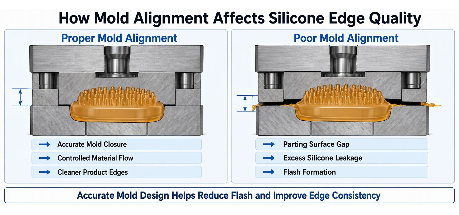
Position Parting Lines Away from Important Visible Surfaces
Every two-plate mould leaves a line, so the practical question is where to put it. On a silicone sponge, the natural position is around the widest circumference, which is also the most visible. Moving the line slightly toward the flat base keeps the seam out of the direct line of sight when the product sits on a counter, and it puts the seam in a region where a light trim is less likely to change the silhouette.
On a brush holder, the seam can usually be placed on the underside of the base or on a moulded rib where a slight step reads as part of the design. On a spatula, the handle is forgiving and the blade edge is not, so the line belongs on the handle side of the transition.
Optimize Cavity Design for Thin and Detailed Features
Thin features benefit from being fed directly rather than through a long flow path. Where a part has a delicate rim, positioning the charge so that the rim fills last, at the lowest possible pressure, reduces the driving force available to push compound into the parting gap.
Detailed surface features also deserve a second look before steel is cut. A fine texture or a sharp internal corner that cannot be reproduced consistently is a defect source, not a design feature, and simplifying it often improves the edge quality of the rest of the part.
How Should Silicone Makeup Tools Be Inspected After Molding?
Edge inspection is often reduced to a visual pass under room lighting, which is why disputes happen later. A short, repeatable routine produces far more reliable agreement between supplier and buyer than a longer inspection with no defined method.
Check Edge Smoothness Before and After Trimming
Inspect the part as it comes out of the mould first. That tells you what the tool is producing. Then inspect after trimming, and compare. If the untrimmed edge is acceptable and the trimmed edge is not, the problem is the trimming method. If the untrimmed edge is already inconsistent, trimming cannot fix it and the process needs attention instead.
Run a fingertip along the edge in one direction, then the other. A trim that has cut into the product outline feels sharp in one direction and smooth in the other, because the cut edge has a burr. A properly removed flash line feels uniform in both directions even where a faint seam remains.
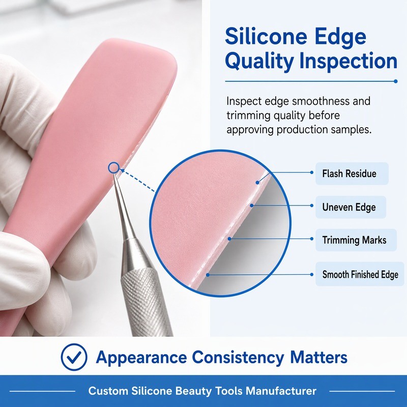
The inspection in the image separates four conditions that are easy to confuse at normal viewing distance: residual flash film, an uneven contour, visible trim marks and a clean finished edge. Naming them separately is what makes an acceptance standard usable, because each one has a different remedy.
Low-angle light helps more than magnification here. A raking light from the side exaggerates any film or step along the edge, while straight-on lighting tends to hide exactly the defect you are looking for.
Compare Appearance Across Samples and Production Batches
A single golden sample is not enough on its own, because it does not describe how much variation is acceptable. Keep a small reference set: one approved sample, one marginal sample and one rejected sample, each labelled with the specific condition it demonstrates. That set removes most of the ambiguity in later discussions and gives an inspector something to compare against instead of a memory.
Dimensions deserve the same treatment. Silicone parts are elastic, so a calliper reading depends on how much pressure is applied. Agreeing on the measurement method, and on the tolerance class the part belongs to, matters as much as agreeing on the nominal dimension. ISO 3302-1:2014 sets out dimensional tolerance classes for moulded solid rubber products and is a useful common reference when a drawing has no class stated.
Pay Attention to Areas That Contact Skin or Makeup Products
Finally, inspect where the tool is used. The head edge of a mask brush, the working face of a silicone sponge and the blade of a spatula should be checked at higher magnification and under stronger light than the rest of the part. A defect that is invisible on the body of the tool can be obvious at the point of contact, and that is the area a customer photographs when they complain.
What Should Buyers Confirm Before Ordering Custom Silicone Makeup Tools?
Most edge disputes are decided before the purchase order, in the documents that were or were not exchanged. Four items are worth settling early.
Define Acceptable Flash and Edge Finishing Requirements
State where a seam is permitted, how thick residual flash may be, and whether trimming is manual or by a defined method. A written statement is more useful than a verbal "clean edges", because it can be inspected against.
Confirm Mold Structure and Trimming Methods Before Sampling
Ask how many plates the tool has, where the parting line will sit, and how flash will be removed. These answers predict the edge you will receive more reliably than a rendered image.
Evaluate Sample Consistency Before Moving to Mass Production
Request parts from more than one cavity and from more than one run. A sample set that has been hand-selected tells you what the process can do at its best, not what it will deliver across an order.
Prepare the Inputs That Drive the Decision
A 2D drawing and a 3D file, the critical dimensions and the intended edge thickness, the appearance requirement and the level of trim marking you will accept, the material hardness and colour, and the expected order quantity. With those in hand, a supplier can evaluate feasibility rather than guess at it.
Frequently Asked Questions About Flash on Silicone Makeup Tools
Why does silicone flash appear around the edges of molded products?
Because the compound flows under pressure and will enter any gap at the parting surface that is easier to fill than the remaining cavity volume. Excess charge, a locally open parting line, or a thin edge section that requires high filling pressure all create that condition.
Can silicone product flash be removed completely after molding?
The visible film can normally be removed, but a moulded part will still carry a seam where the two halves met. What can be controlled is how visible that seam is, how much material is left around it, and whether the removal leaves a mark. A part with no seam at all would require a different mould concept.
Does mold precision affect the edge quality of silicone makeup tools?
Yes, particularly the flatness and finish of the sealing land and the alignment of the two halves. Precision alone does not guarantee a clean edge, though, because loading volume and cure conditions can produce flash on a well-made tool.
How can buyers reduce edge defects in custom silicone beauty tools?
By agreeing on a written edge standard, placing the parting line deliberately during design, reviewing samples from more than one cavity and run, and treating trim quality as part of the acceptance criteria rather than an afterthought.
What This Means for Your Next Development Cycle
Edge quality is decided in three places, in this order: the product drawing, the mould design, and the process settings used on the day. Trimming sits at the end and can only remove what should not be there. If the film is thick, the cause is upstream, and a heavier trim will simply replace a flash problem with a contour problem.
The practical route for a brand developing a silicone beauty tool is to bring the drawing and a reference sample to the tooling discussion, agree which edges are visible and which are not, and ask for a sample set that shows the natural variation of the process. FromRubber works on custom silicone beauty tools at exactly this stage, reviewing product structure and mould feasibility before steel is cut. If you would like a second opinion on an edge specification or a mould layout, our engineers can review drawings and samples and reply with a written assessment. Reach the team on WeChat or WhatsApp at +86 18676210913, or use the inquiry form to send files.
| Cause | What happens at the edge | First thing to check |
|---|---|---|
| Poor mold closure | Compound escapes through a local gap at the parting surface | Sealing land flatness and guide pin wear |
| Excess material loading | Surplus charge has nowhere to go but outward | Charge weight against cavity volume |
| Unstable curing conditions | Material is still moving, or skins over before the cavity packs | Platen temperature and cure time record |
| Complex product geometry | Thin edge needs high pressure to fill, so it leaks first | Edge section thickness and venting |
About the source
FromRubber is the brand of Dongguan Bohao Electronic Technology Co., Ltd., a custom silicone and rubber parts manufacturer that produces compression-moulded components for beauty, electronics and industrial customers. The notes above come from production work on custom silicone tooling rather than from a general materials handbook. The parts discussed are grouped under custom silicone rubber parts. For a specific project, the engineering team can be reached on WeChat or WhatsApp at +86 18676210913.
Sources and further reading
- ISO 3302-1:2014, Rubber — Tolerances for products — Part 1: Dimensional tolerances. ISO 3302-1:2014 standard page
- FromRubber technical note on parting line design and flash control
- FromRubber production note on flash control and deflashing methods