Why Does Button Spacing Matter When Designing Silicone Keypads for Patient Monitoring Devices?
- Share
- publisher
- FromRubber
- Issue Time
- Nov 13,2026
Summary
Button spacing on a patient monitor is a usability decision that has to survive as a manufacturing dimension. The article separates pitch from clear gap, explains how membrane webs couple neighbouring keys, and lists what OEMs should specify before tooling.
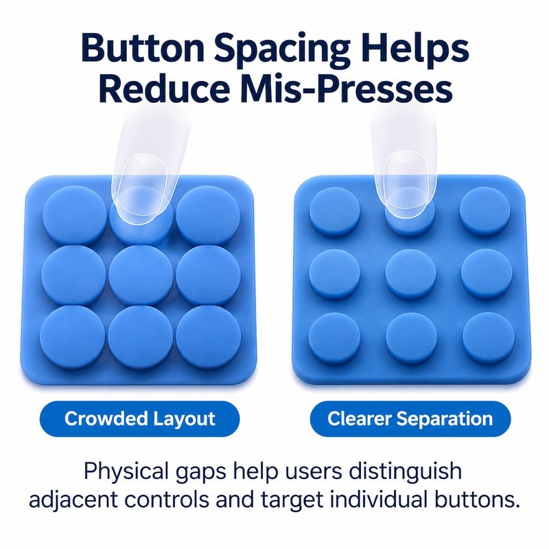
Ask a designer how far apart the keys on a monitor should be and the answer is usually a number in millimetres, taken from an earlier project. Ask a nurse and the answer is different: two controls that cannot be hit by the same thumb, and one alarm key that can be found without looking. The first answer describes a drawing. The second describes what happens at three in the morning when the patient has moved and the cable is short.
On patient monitoring equipment, the gap between two keys is not decoration. It is the physical boundary that decides whether a press lands on the intended control. When that boundary is too narrow, the error does not appear in a specification sheet; it appears as a changed setting that nobody remembers changing. This is why silicone keypads for patient monitoring devices are reviewed against use rather than against a table of millimetres. Silicone keypad spacing is the cheapest way to build hierarchy into a part, and the first thing lost when a housing shrinks.
Why Is Button Spacing Important in Patient Monitoring Devices?
A monitor panel is a small area carrying functions of very unequal consequence. Selecting a waveform is routine; silencing an alarm or zeroing a pressure channel is not. When all keys are the same size and evenly distributed, the panel offers no physical hierarchy, and the operator has to rely on reading the legend each time. Spacing is the cheapest way to build that hierarchy into the part.
Reducing Accidental Button Activation
Adjacent keys are not independent when they share a membrane. Press one and the sheet around it deflects a little; if the neighbouring key sits close enough, its dome can begin to load. The effect is worst on the diagonal, where two keys compete for the same corner of web. Widening the clear gap between key edges does two things at once: it lowers the chance of sharing load, and it gives the fingertip a place to rest between targets.
Visual separation is not the same as tactile separation. Printed boundaries and coloured zones help in daylight, but a gloved finger reads shape and height, not colour. If the gap between keys is filled by a raised ridge or a flush land of the same height as the keytops, the finger loses the boundary that the eye can see.
Put two keypads on a bench with the same key count and the same legends, one crowded and one opened up, and the difference is measured by asking people to press a named key without looking. The crowded panel produces hits on the neighbour; the open panel produces hits on the intended key. That simple test is a better specification input than a millimetre target chosen by habit.
It also shows where spacing cannot help. If two keys of very different importance are the same size and the same height, no amount of gap will stop a hurried press from choosing the wrong one. The fix there is shape and height, which the next section covers.
Making Frequently Used Controls Easier to Reach
Reach and spacing pull in opposite directions on a handheld monitor. Opening the gap between keys spreads the panel, which pushes some controls towards the edge of the thumb arc. The compromise is to spend the available gap where it protects a consequential action, and to accept tighter spacing among keys that are rarely touched and never pressed in a hurry.
Grouping helps more than uniform spacing. A cluster of arrow keys for navigation can sit closely together because the finger learns the cluster as one shape and moves inside it by position. The silence-alarm key, by contrast, benefits from an isolated position with clearance on all sides, because it is pressed under time pressure and often without a direct look.
Maintaining a Compact Control Panel Without Crowding Buttons
When the housing shrinks, the first instinct is to reduce every key by the same percentage. That preserves the drawing and destroys the usability, because the clear gap shrinks faster than the key: at small sizes, a fixed wall and a fixed land consume a larger share of the pitch. A panel that felt open at 12 mm keys feels fused at 8 mm keys even though the layout looks proportionally identical.
The alternative is to reduce the number of keys on the main surface. Secondary functions can move to a menu, to a long-press, or to a side-mounted row that is out of the way of the primary operating area. Every function removed from the crowded zone buys gap for the functions that remain.
What Design Factors Determine the Right Spacing Between Silicone Keypad Buttons?
Button Diameter and Physical Separation
Two numbers describe the same layout and they are routinely confused. Centre-to-centre distance is the pitch used to place keys on a drawing. The clear edge gap is what the finger actually experiences, and it equals the pitch minus the key diameter, minus any skirt or raised rim that belongs to the key. A 12 mm pitch with 10 mm keytops leaves a 2 mm edge gap before draft is considered; the same pitch with 8 mm keytops leaves 4 mm.
Because drawing dimensions are usually given as pitch, a layout can look generous on paper and still feel fused in the hand. Reviewing the clear gap, and reviewing it at the base of the key rather than at the top of the keytop, is what keeps the two numbers honest.
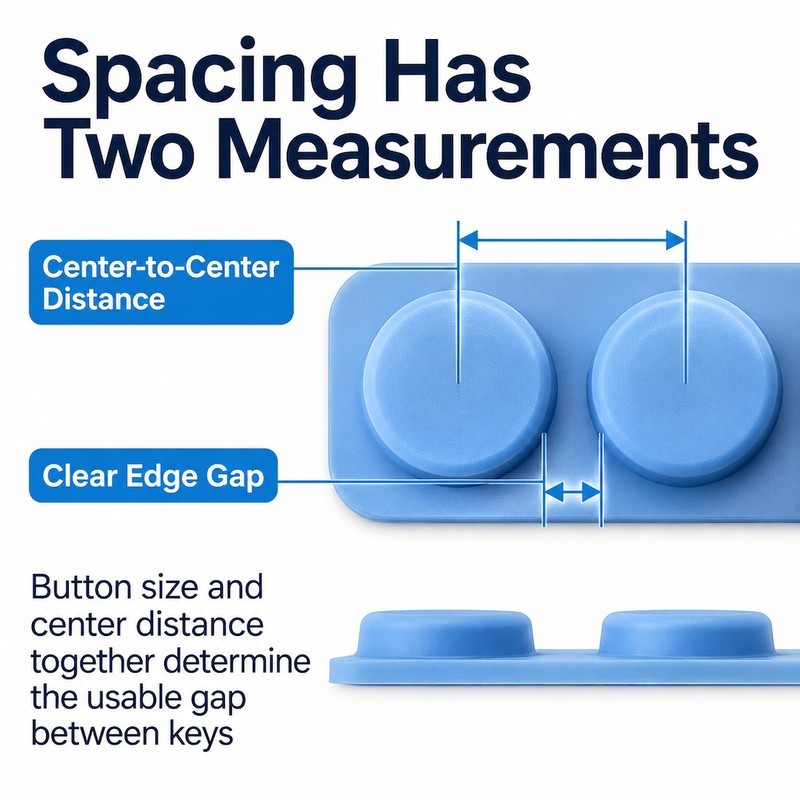
Write both numbers on the drawing. A single pitch value forces the toolmaker to infer the gap, and inference is where a well-intentioned correction turns into a layout change. Adding the clear gap as a referenced dimension also gives the inspection team something to measure on the first article, which is where spacing problems are cheapest to find.
Where a key has a moulded skirt or a raised rim, dimension the gap at the widest point of the feature. A skirt that flares by half a millimetre consumes a full millimetre of the gap between two neighbours, and it does so invisibly if only the keytop is dimensioned.
Button Height and Tactile Differentiation
Height is the second boundary. A key that stands 1.2 mm above the land is easy to find and hard to overshoot; a key that stands 0.3 mm above the land asks the finger to be precise. On a panel where two adjacent controls must not be confused, giving them different heights is more reliable than giving them different legends, because height is read before the eye arrives.
Differentiation can be built into the keytop as well: a concave dish on a frequently used key, a raised bar on a directional key, a recessed ring around a function that should require intent. These features are moulded, so they cost nothing per part once the cavity is cut, and they survive cleaning in a way that printed legends sometimes do not.
Silicone Membrane Structure Between Adjacent Buttons
The web between keys is a structural member, and its width decides how much the neighbours share. A wide, thick web couples the keys: press one and the other rises slightly, which the finger reads as a soft, connected panel. A narrow web with a defined hinge line lets each key travel on its own, at the cost of a thinner section that has to be filled reliably in the mold.
On compact medical panels this is the detail that most often decides between a usable layout and a frustrating one. Two keys can be 2.5 mm apart on the drawing and still behave as one control if the web between them is stiff enough to transmit load.
| Factor | What it controls | Where it is actually set |
|---|---|---|
| Key diameter | Size of the target and how much of the pitch it consumes | Keytop dimension on the layout drawing |
| Clear edge gap | Whether a thumb can isolate one key from its neighbour | Pitch minus diameter, measured at the widest skirt |
| Key height | Whether the boundary can be found by touch | Keytop height and bezel depth |
| Web width | How much load adjacent keys share | Membrane section between keys |
| Legend placement | Whether the correct target can be confirmed visually | Printed or moulded symbol inside the keytop |
How Can Designers Balance Button Spacing and Keypad Size?
Prioritize Controls According to Operating Frequency
Before any dimension is fixed, list the controls in order of how often they are used and how much damage a wrong press causes. The list usually separates into three groups: pressed constantly, pressed under pressure, and pressed rarely. Only the first two deserve space on the main surface; the third can be smaller, grouped, or moved behind a menu.
This ordering also settles arguments about uniformity. A panel does not have to be uniform to look professional; it has to be predictable. Uneven spacing that follows function reads as design, while even spacing that ignores function reads as a grid.
Adjust Button Shapes for Better Space Utilization
Round keys use space generously because the corners of their bounding squares are empty. Rectangular or elongated keys use that space, and they also give the finger a direction. A row of three elongated keys can carry more legend area and more separation than a row of three circles in the same width, provided the webs between them are designed with the same care.
Shape changes must be followed through into the membrane. A long rectangular key needs support along its length, or it will tilt when pressed at one end. That usually means a pair of domes under the keytop or a stiffening rib, both of which change the feel and have to be reviewed together with the spacing.
Coordinate the Keypad With the Housing and PCB Layout
Spacing cannot be finalised before the electronics are placed. A key that sits well in the keypad can end up above the edge of a PCB cut-out, or beside a connector tall enough to limit its travel. The usual failure is a panel that passes on the bench and fails after assembly, because the board sits a few tenths higher than the drawing assumed.
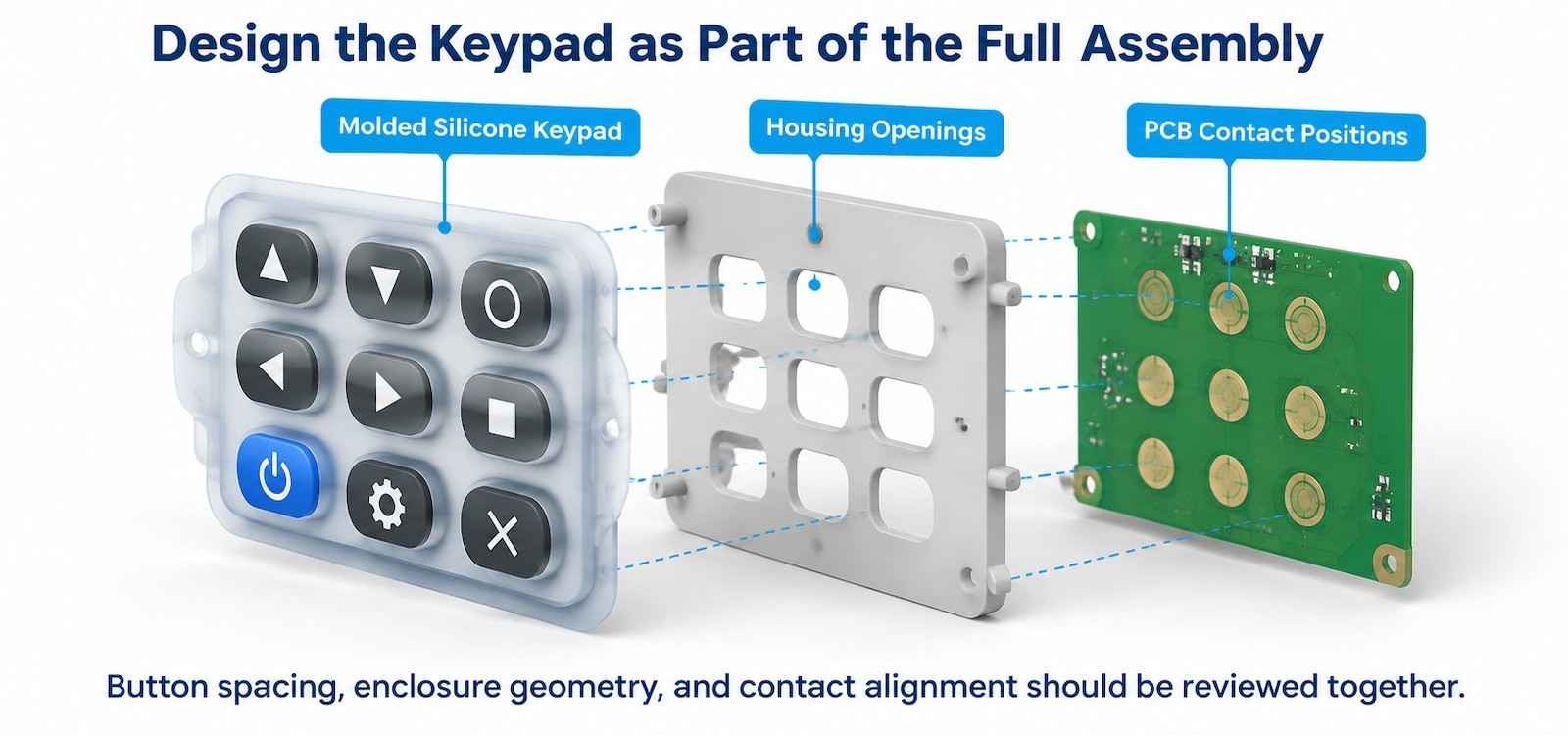
The practical method is to build a stack drawing with the keypad, the housing opening and the PCB contact positions on separate layers, then check that every key has the same clearance to its opening and the same over-travel to its pad. Where a key differs, mark it and decide whether the difference is intentional. Differences that were never decided are the ones that generate complaints.
What Manufacturing Issues Can Affect Button Spacing and Alignment?
Dimensional Deviations During Silicone Molding
Silicone shrinks as it cures, and the shrinkage is not perfectly uniform across a part with thick and thin regions. On a long keypad, the cumulative effect can move a key at one end by a few tenths relative to the other end. On a panel where the clear gap is only 2 mm, a drift of 0.2 mm is ten percent of the usable space.
Cavity accuracy sets the starting point, but repeatability sets the outcome. A tool that produces the right dimensions on the first shot and drifts over a thousand is a bigger problem than one that is slightly off but stable, because the second can be corrected by a single tool change while the first produces a slow stream of marginal parts.
Keypad Positioning During Assembly
A keypad that can move inside its housing will eventually move. Locating features, whether pins, moulded tabs or a shaped perimeter, remove that freedom. Without them, the assembly operator centres the part by eye, and the first key takes the tolerance that the last key needed.
Alignment to the PCB matters as much as alignment to the housing. A key can look perfectly centred in its opening and still sit off its pad if the board is located from a different datum. Reviewing both datums on the same drawing is the only way to catch that before production.
Flash and Uneven Edges Between Adjacent Buttons
Flash at the parting line is the quiet thief of clear gap. A hairline of excess material around a key edge reduces the space the finger can use, and on a closely spaced panel it can bridge the gap visually and physically. It also stiffens the membrane locally, which changes the press feel of that key alone.
Parting line placement should be chosen with the gap in mind: put it on a land rather than on a key wall where possible, and specify the finishing operation. Trimming by hand removes the visible flash but leaves a variable edge; trimmed in the tool or by a fixture, the edge is consistent from part to part.
What Should Medical Device OEMs Specify Before Custom Keypad Production?
Confirm Button Dimensions and Center-to-Center Distances
Provide a layout drawing with key diameter, key height, pitch, clear edge gap, tolerance and the datum used for each. State which dimensions are functional and which are reference. A drawing where every dimension carries the same tolerance gives the toolmaker no guidance about where to spend precision.
Identify Operating Conditions and User Requirements
Say whether operators wear gloves, whether the panel is cleaned with liquids, whether the device is handheld or cart-mounted, and which functions must never be triggered accidentally. These answers change spacing, height, web width and surface finish, and they are much cheaper to supply at the drawing stage than to discover during a use evaluation.
Evaluate the Complete Keypad Assembly
Review the sample in the housing, with the real PCB and the real gasket, and ask the people who will use it to press it. Check that each key can be isolated by touch, that the consequential keys are clearly different from their neighbours, and that a gloved press does not catch two keys at once.

Frequently Asked Questions About Silicone Keypad Spacing
What is the difference between button spacing and center-to-center distance?
Centre-to-centre distance is the pitch between key centres on a drawing. Button spacing, or clear gap, is the open distance between the outer edges of two adjacent keys. The clear gap is what a finger can use, and it equals the pitch minus the key diameter and any skirt or rim.
Can silicone keypad buttons be placed closer together without affecting operation?
Sometimes, if the web between them is narrowed and hinged so that each key travels independently, and if the keys are given different heights or profiles. Below a certain gap, the membrane couples the keys regardless of profile, and the panel starts to behave as one large key.
How does button height help prevent accidental activation?
A raised key presents an edge that the finger meets before the keytop, so a sliding thumb stops at the boundary instead of continuing onto the neighbour. Height difference between neighbouring keys is read faster than a printed legend and is unaffected by cleaning.
Does silicone hardness affect the separation between adjacent buttons?
A softer compound allows more local deflection, so a press on one key disturbs its neighbours more. Hardness does not change the geometry, but it changes how much the geometry matters. On closely spaced panels, a slightly firmer compound often preserves isolation better.
Can custom silicone keypads accommodate compact medical device housings?
Yes, by moving secondary functions off the main surface and using shaped keys that fill the available area. The limit is not the housing size but the number of controls that must remain directly reachable. Our notes on keypads for medical diagnostic devices describe the same trade-off from the feedback side.
Where Spacing Sits in the Design File
Spacing is a usability decision that has to survive as a manufacturing dimension. Silicone keypad spacing only holds when the clear gap, the key heights and the web widths are written on the drawing with tolerances that match their importance; then the panel stops depending on the operator's eye and starts depending on the tool. IEC 60601-1 addresses the basic safety and essential performance of the device rather than giving a millimetre figure for key spacing, and IEC 62366-1 approaches usability as a process of use-related risk analysis, so the number itself remains an engineering judgement that the OEM and the moulder have to make together.
FromRubber is operated by Dongguan Bohao Electronic Technology Co., Ltd. in Dongguan, Guangdong. FromRubber moulds keypads for medical diagnostic and patient monitoring equipment in Dongguan, on 32 hydraulic presses across two plants, with in-house CNC for cavity work and a management system certified to ISO 9001:2015, ISO 14001:2015 and IATF 16949:2016. Component approval and device approval remain with the OEM. What we can do early is read the layout against the housing and tell you which keys will fight each other before the cavity is cut.
Send the layout, not just the keypad
A housing section and a PCB placement drawing tell us more than a keypad drawing alone. Phone, WhatsApp or WeChat: +86 18676210913, or upload through the contact page.
Related Reading
Sources and Test Methods Referenced
- IEC 60601-1:2005+AMD1:2012+AMD2:2020, Medical electrical equipment, Part 1: General requirements for basic safety and essential performance. IEC.
- IEC 62366-1:2015+AMD1:2020, Medical devices, Part 1: Application of usability engineering to medical devices. IEC.
- IEC 60529:1989+AMD1:1999+AMD2:2013, Degrees of protection provided by enclosures (IP Code). IEC.
- ISO 2768-1:1989, General tolerances, Part 1: Tolerances for linear and angular dimensions without individual tolerance indications. ISO.
- ISO 23529:2016, Rubber, general procedures for preparing and conditioning test pieces for physical test methods. ISO.
- Editions checked against the ASTM, ISO and IEC publisher listings in November 2026.