fromrubber-How To Make Silicone Rubber Parts
- Share
- publisher
- karl
- Issue Time
- Jun 12,2024
Summary
How silicone rubber parts are actually made: compression, injection and liquid silicone moulding compared, the five project steps from drawing to production, and the data a supplier needs before quoting.

Most buyers asking how silicone rubber parts are made expect a single answer. There are three production routes, and the choice between them decides tooling cost, cycle time, achievable tolerance and the minimum volume that makes sense.
This article explains how the route is chosen, then walks through the five steps a custom part goes through from drawing to production, with the data needed at each step.
What Decides How Silicone Rubber Parts Are Made
Three variables choose the process: part size, annual volume and the tolerance the design needs. Small parts in high volume justify a multi-cavity tool and an injection or LSR press. Large parts in low volume are usually compression moulded from a simple tool, because the tool cost dominates the economics.
Geometry matters as well. Undercuts, thin walls and inserts all change the tool and the demoulding method, and some of them are only practical in one route.
None of this is a quality hierarchy. A well-run compression tool produces parts as consistent as an LSR cell; the difference is how much the tool and the cycle cost, and what the material can do.
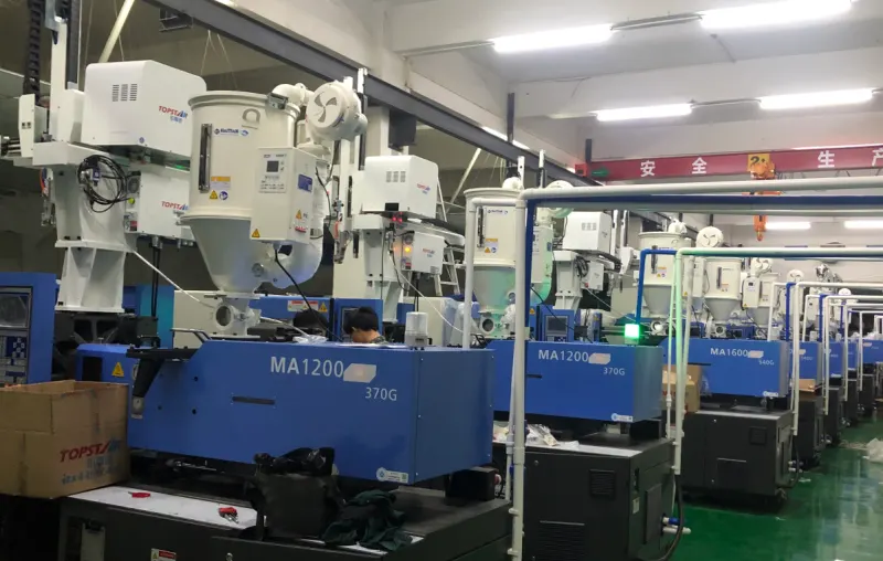
Compression, Injection or LSR for Silicone Rubber Parts
| Route | Typical fit | Trade-off |
|---|---|---|
| Compression moulding | Large parts, low to medium volume, simple shapes | Cheapest tool, longest cycle, more manual handling |
| Injection moulding (HCR) | Medium parts, medium to high volume | Higher tool cost, shorter cycle, better repeatability |
| Liquid silicone (LSR) | Small, precise parts at high volume | Expensive metering equipment, excellent consistency, tight tolerance |
Choosing the process for your silicone rubber parts
Start from the annual volume and the tolerance, not from the part name. A gasket that must hold a 0.1 mm section tolerance at 50,000 pieces a year is an LSR or injection conversation. The same gasket at 500 pieces a year is compression moulded and inspected, because the tool cost of the other routes cannot be recovered. When volume is uncertain, a prototype tool in the cheaper route proves the design before the production route is committed.
From Drawing to Silicone Rubber Parts: the Five Steps
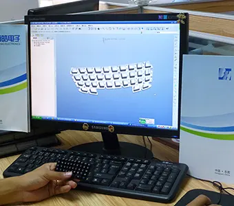
1. Drawing review. The supplier checks wall thickness, radii, undercuts, parting line position and tolerance stack, and returns a DFM note. This is the cheapest moment to change anything.
2. Quotation and tooling. Cavity count, material grade, secondary operations and inspection scope are fixed, and the tool is designed with a gate and parting line that suit the part rather than the press.
3. T0 or prototype sample. A simple tool or a machined surrogate produces the first parts. The purpose is to prove geometry and fit, not to prove the production process.
4. Sample approval. Dimensions, appearance and function are measured against the drawing, and the customer approves or returns with a marked-up report.
5. Production tool and run. Production steel is cut, first article is measured, and the process is frozen with a control plan for the parameters that affect the part.
What to Send Before Silicone Rubber Parts Are Quoted
A STEP model, a 2D drawing with the tolerances that matter, the material family and hardness, the colour, the annual volume, and the secondary operations the part needs. Add the application, because a seal for a static joint and one for a moving joint can share a drawing and need different compounds.
If a similar part already exists, send a sample. Reverse engineering a sample is fast when the geometry is simple and slow when it is not, and knowing which case applies changes the quote.
For parts that combine silicone with another material, such as a keypad on a PCB or a gasket bonded to plastic, say so early: those combinations move the project into over-moulding and change both tooling and process.
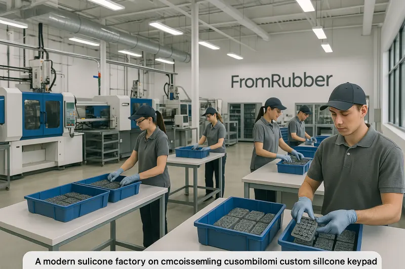
Documents that make a silicone rubber parts project run smoothly
- STEP or IGES model plus a 2D drawing with critical dimensions flagged.
- Material grade, hardness band and the reason for the choice.
- Colour reference and surface finish, including any printing or etching.
- Volume forecast by quarter, not only an annual number.
- Inspection requirement: which dimensions are checked, and by what method.
Can silicone rubber parts be made without a tool?
For small quantities, yes, using a machined or 3D-printed surrogate or a simple prototype mould. Those parts are useful for fit checks but do not represent production tolerance, material properties or surface finish.
How long does a silicone rubber parts project take?
The moulding itself is quick; the elapsed time is dominated by drawing review, tool making, sampling and approval. Prototype parts are usually the fastest step, and approval iterations are the most common cause of delay.
Silicone rubber parts are made by one of three routes, and the route is chosen from volume, size and tolerance rather than from the part name. Review the drawing before the tool is designed, approve a T0 sample against measured data, then freeze the process. Send the model, the drawing, the material, the colour and the volume, and the rest of the conversation is engineering rather than guesswork.