How to Design Custom Conductive Silicone Buttons
- Share
- publisher
- karl
- Issue Time
- Jun 18,2025
Summary
A practical design sequence for a conductive silicone button: contact geometry against the PCB pad, carbon pill height, force and travel, legend options, tooling notes and the checks to run before mould steel is cut.
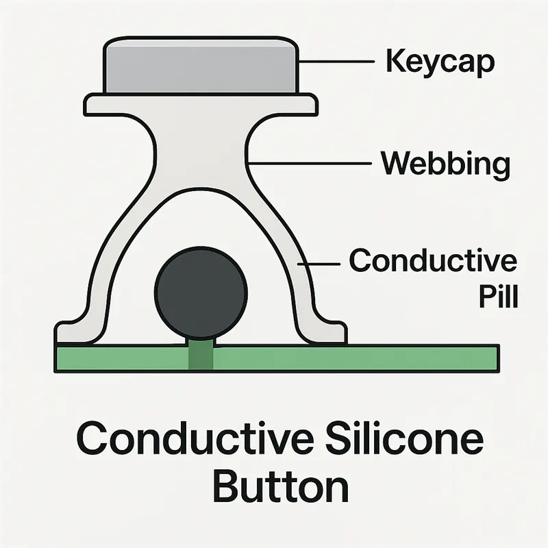
A conductive silicone button is a single moulded key that carries a carbon-filled pill on its underside, so pressing it shorts a pad pair on the board below. The design work is not drawing the shape. It is deciding the pill area against the pad geometry, the height that separates them at rest, and the force that brings them together reliably for the life of the product.
This guide sets out the sequence we use when a customer sends a PCB and a key layout but no button specification. It is written for the engineer who has to hand a drawing to a toolmaker and defend it later.
What Defines a Custom Conductive Silicone Button
Five variables define the part: the substrate (usually 40 to 70 Shore A silicone), the pill compound and its geometry, the web that connects the key body to the mat, the legend method, and the surface finish. Only one of these, the pill, is electrical; the other four decide whether the pill stays in contact long enough and at the right pressure.
That is the reason a conductive silicone button is a mechanical design task first. When a button reads open on some units and closed on others, the compound is rarely at fault. Either the pill is not reaching the pads, or it is reaching them with too little force because the web is too stiff or the key is over-supported.
Choose the Contact Geometry Before the Material
The PCB pad is the constraint. Interdigitated fingers with a 0.3 to 0.5 mm gap need a pill that covers the whole pattern with margin, typically 1.5 to 2 times the pattern diameter, and the pill must sit flat rather than dome-shaped. A domed pill touches on one line, and that line moves as the key rocks.
Pill height above the board at rest controls pre-travel. Too little and the button is pre-loaded by assembly tolerance, which means it may read closed before anyone presses it. Too much and the operator has to push through dead travel, which feels like a faulty key. A protrusion of 0.1 to 0.3 mm below the surrounding skirt is the usual starting band, adjusted once the real stack of mat, spacer and PCB is known.
Matching the conductive silicone button to the PCB pad
| PCB condition | Button consequence | Design response |
|---|---|---|
| Pad gap 0.5 mm, HASL finish | Oxide film builds on the tracks | Slightly larger pill and higher contact force |
| Gold-plated pads | Low, stable contact resistance | Smaller pill, lower force, longer life |
| Board warp above 0.2 mm | Uneven contact across the pad | Shorter pill protrusion plus a stiffer key body |
| Domed or raised pads | Pill touches on a line | Flat pill face, larger area |
| Carbon-printed tracks | Higher track resistance | Specify the total loop, not just the switch |
Rule of thumb: Decide the closed-resistance limit and the test force first, then choose pill size. Choosing the pill first and measuring what comes out leaves no way to reject a batch that is technically inside the drawing.
Setting Force and Travel for a Conductive Silicone Button
Actuation force for a hand-operated control normally falls between 150 and 400 gf. Below that band a thumb resting on the panel can trigger the key; above it, operators press with the side of a thumb and wear the legend faster. The figure to specify is the force at the moment the pill contacts the pad, because that is the force that sets contact resistance.
Travel should leave overtravel. If the key bottoms out at the same instant the pill touches, every tolerance in the stack becomes an electrical variable. A useful target is that closure happens at roughly 60 to 75 percent of total travel, leaving the rest as usable overtravel.
Web thickness is the lever for both. Thinning the web lowers the force and sharpens the snap; thickening it does the reverse. Change one and the other moves, which is why force and travel should be specified together on the drawing rather than as separate notes.
Legends, Surface Treatment and Tooling

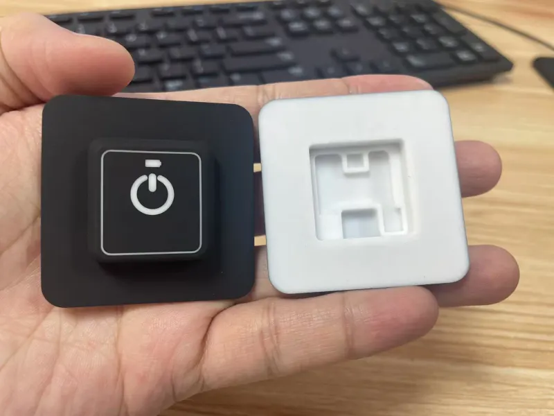
Legends are either moulded in relief, screen printed, or laser etched through a coated surface. Moulded relief survives everything but cannot hold fine detail below roughly 0.4 mm stroke width. Screen printing gives sharp graphics and colour but sits on the surface, so it wears first on the most-used key. Laser etching through a two-layer coating gives a durable legend and is the usual choice for backlit keys.
Surface treatment changes feel more than function. A matte texture hides fingerprints and tool marks; a gloss finish shows every flow line. If the button must resist alcohol wipes, say so at quotation stage, because the coating and the printing ink both change.
Tooling for a single button is a small investment compared with the cost of a wrong gate position. A gate that fills the key body before the web can leave a weld line across the legend, and no amount of printing hides it. Review the gate layout on the tool drawing, not only on the part drawing.
How to Brief a Supplier on a Custom Conductive Silicone Button
The five inputs a conductive silicone button quote needs
- PCB layout with pad dimensions, finish and track resistance, plus the scan circuit's resistance window.
- 2D drawing with force, travel and closed resistance, each with a tolerance.
- Key layout, legend artwork and the colour reference for body, legend and any backlight.
- Environment: cleaning agents, temperature range, UV exposure and expected press count.
- Assembly method: mat clamped by housing, adhesive, or captured under a bezel.
With those five inputs a supplier can quote a construction instead of a shape. If the layout is still open, our notes on conductive keypads in industrial panels explain how the same pill behaves at panel level, and the hardness selection guide covers the substrate choice that sits underneath it.
Does a conductive silicone button need a click?
Not always. A crisp snap confirms the press to the operator, but a flat, low-travel button with a short overtravel can be preferable on a sealed panel where a click would be masked by gloves. Decide from the operator's hands, not from the datasheet.
Can the carbon pill be replaced by a metal dome?
Yes, and a metal dome gives a sharper click and lower resistance. It also adds an assembly step, a corrosion path and a rattle risk. Silicone pills win where sealing, cost and flatness matter more than the last few ohms.
Draw the pad, not the button. Fix the contact area, the protrusion and the force at contact, keep part of the travel as overtravel, and choose the legend process from the cleaning routine. That sequence produces a conductive silicone button that can be inspected against numbers, which is the only kind that survives a production run.