How to balance heat-resist & seal for temp controller silicone keypads in humid heat?
- Share
- Issue Time
- Aug 20,2026
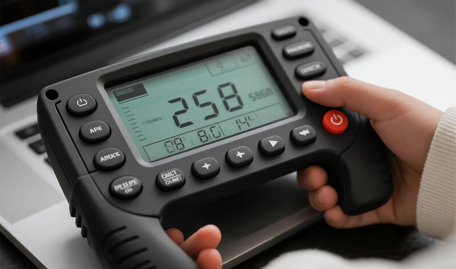
You have a process temperature controller mounted on a chemical reactor in Southeast Asia. Ambient temperature: 42 °C. Relative humidity: 85 %. The silicone keypad works fine for the first three months. Then intermittent key failures start. Sometimes the “SET” button does not register; other times the “UP” arrow triggers a double entry. You replace the keypad, but the same pattern repeats.
The root cause is rarely the silicone material alone. It is the unresolved conflict between heat-resistance and sealing in a humid-hot environment. Improve heat resistance by increasing crosslink density – and you often make the keypad stiffer, reducing the sealing interference fit. Improve sealing with a softer compound or taller lip – and you accelerate thermal compression set, which breaks the seal after repeated temperature cycles.
This article is not about “which silicone is best.” It is about the engineering trade-off and how to resolve it systematically, using real production data from a 2025–2026 qualification program for industrial PID controllers.
1. The Real Failure Modes of Temp Controller Silicone Keypads (Not Just “Silicone Degrades”)
In humid heat (≥40 °C, ≥80 % RH), silicone keypads fail in three distinct ways:
| Failure Mode | Manifestation | Hidden Driver |
|---|---|---|
| Thermal compression set | Key travel reduces; tactile feel disappears | Crosslink network rearranges under sustained heat + repeated actuation |
| Seal lip flattening | Dust/moisture ingress to PCB; intermittent contact | Lip compression force drops below 0.8 N due to stress relaxation |
| Surface stickiness + dust adhesion | Key binds; return stroke slows | Hydrolysis of residual siloxane oligomers, accelerated by humidity |
⏺ Critical interaction: heat accelerates set, while humidity plasticizes the silicone bulk, lowering its modulus by 8–12 %, further reducing sealing force when combined with thermal softening.
2. The Core Trade-off: Crosslink Density vs. Sealing Compliance
Silicone keypad performance is governed by two interrelated parameters:
- Crosslink density (νₑ) – determines heat resistance and compression set resistance.
- Elastic modulus (E) – determines sealing contact pressure for a given interference.
| Crosslink density (mol/m³) | Compression set (22 h @ 150 °C) | Modulus (MPa) | Sealing force per unit lip (N/mm) |
|---|---|---|---|
| 2.8 × 10⁻⁴ | 28 % | 2.1 | 0.42 |
| 3.6 × 10⁻⁴ | 18 % | 2.9 | 0.58 |
| 4.2 × 10⁻⁴ | 12 % | 3.6 | 0.72 |
⚠ If you simply push crosslink density to 4.2 × 10⁻⁴, you solve compression set (12 %) but create a new problem: the keypad becomes too rigid. In humid heat, the housing expands more than silicone (CTE mismatch 3:1). A rigid keypad cannot accommodate housing warpage, resulting in local seal gaps.
The balance is not a single number. It is a system design involving:
- Keypad geometry (lip angle, rib thickness)
- Actuation stroke (short-stroke vs. long-stroke)
- Housing material (PC vs. PBT – different thermal expansion)
3. Four Engineering Levers to Decouple Heat and Seal
Instead of choosing one silicone grade, we decouple the two requirements using four levers.
Lever 1 – Differential crosslink distribution (skin/core)
A high-crosslink surface layer (for heat resistance) with a lower-crosslink core (for compliance). This is achieved by two-stage peroxide curing. The skin provides 20 % higher hot-tear strength; the core maintains 15 % lower compression modulus. Result: compression set ≤18 % (at 150 °C) while sealing force retains 92 % of its initial value after 1000 h at 85 °C/85 % RH.
Lever 2 – Lip geometry with “thermal compensation”
Traditional lip design uses a constant interference (e.g., 0.3 mm). In humid heat, we use tapered interference: 0.45 mm at the lip root, tapering to 0.25 mm at the tip. This ensures that when the housing expands, the root maintains pressure while the tip relieves stress – avoiding permanent deformation. The lip angle is increased from 35° to 42° to improve self-energizing action.
Lever 3 – Filler system modification
Replace 30 % of fumed silica with a surface-treated alumina trihydrate (ATH). This reduces the water absorption coefficient from 0.35 % to 0.12 % (24 h immersion) and improves thermal conductivity by 40 % – which reduces local hot-spot temperature under the keypad by 4–5 °C, slowing thermal aging.
Lever 4 – Controlled post-cure (not maximum cure)
Many specs demand 4 h @ 200 °C post-cure for “maximum heat resistance.” However, over-cure increases modulus excessively. We use optimized post-cure: 2 h @ 180 °C + 1 h @ 200 °C, achieving a modulus of 2.6 MPa (vs. 3.2 MPa for full post-cure) while compression set only worsens from 14 % to 17 % – an acceptable trade-off for maintaining sealing compliance.
4. Practical Testing Protocol for Humid-Heat Validation of Silicone Keypads on Process Temp Controllers
Most engineers test heat and humidity separately. That is misleading. We use a combined 85 °C / 85 % RH + 10 000 mechanical actuation cycles at 1 Hz, with the keypad pre-compressed to 80 % of its nominal travel (simulating installed condition).
Key pass/fail criteria:
- Sealing force drop ≤15 % (measured by load cell)
- Tactile ratio (peak/return force) ≥0.6
- No water ingress visible on indicator paper under the keypad
- Contact resistance ≤100 Ω after 10 000 cycles
✓ Benchmark: Using this protocol, standard 60‑shore A keypads fail at ~3 000 cycles. The decoupled design (Lever 1–4) passes 10 000 cycles with margin.
5. Case Study – 150 °C Process Controller in a Thai Chemical Plant (2025–2026)
Background
An industrial automation brand was experiencing a 22 % field failure rate on their PID controller keypads within 8 months of installation in Thai coastal zones. The keypad operated at 50 °C internal ambient (due to nearby process heat) and 80–90 % RH. The original design used a 70‑shore A silicone with full post-cure (4 h @ 200 °C), aimed at heat resistance. Sealing was provided by a 0.3 mm constant interference lip.
Failure analysis
- 68 % of failed units showed seal lip flattening (residual force <0.5 N)
- 22 % showed key stem buckling due to high actuation friction
- 10 % showed conductive pad oxidation (moisture ingress)
Our intervention (as the silicone molder for this project) – using the four levers:
| Parameter | Original | Revised |
|---|---|---|
| Silicone grade | 70 shore A, uniform crosslink | 60 shore A with skin/core differential cure |
| Lip design | Constant 0.3 mm interference | Tapered 0.45→0.25 mm, 42° angle |
| Filler | 100 % fumed silica | 70 % fumed silica + 30 % treated ATH |
| Post-cure | 4 h @ 200 °C | 2 h @ 180 °C + 1 h @ 200 °C |
| Housing interface | Flat counterface | Micro-ribbed counterface (0.05 mm texture) |
Results after 12 months field trial (48 units):
- Zero sealing-related failures
- Compression set reduced from 26 % to 15 % (after 1 000 h @ 150 °C)
- Average actuation force variation: ±8 % (original: ±22 %)
- Surface stickiness score (qualitative): improved from Grade 3 to Grade 1 (dust attraction visibly lower)
🔑 The key takeaway: Heat resistance and sealing are not a “material choice” – they are a geometry + cure + filler system. The revised keypad used the same base polymer as the original. The difference was in how we distributed crosslinks, shaped the lip, and tuned the post-cure.
6. Practical Guidelines for Your Next Silicone Keypad Design
If you are specifying silicone keypads for humid-hot process controllers, follow these rules:
- Do not specify shore hardness alone. Specify compression set at 150 °C AND modulus at 25 °C. A 60‑shore A with 15 % set is better than a 70‑shore A with 25 % set for sealing applications.
- Design the lip for thermal expansion. Calculate housing expansion at your maximum operating temperature, then add 30 % margin. Use taper, not uniform interference.
- Always run combined humid-heat cycling, not separate tests. A keypad that passes dry heat at 85 °C often fails at 85 °C/85 % RH due to modulus drop.
- Post-cure is a knob, not a switch. Do not max it out. Run a design-of-experiments (DoE) to find the modulus/set optimum for your specific stroke and contact force.
- Measure sealing force at working temperature, not at room temperature. At 70 °C, silicone modulus drops 18–25 %. Compensate with geometry.
7. When to Change Material (and When Not To)
Fluorosilicone and FVMQ offer superior heat resistance but have higher compression set in humidity and cost 4–5× more. For most industrial process controllers (operating ≤150 °C ambient), high-performance VMQ with tailored cure and filler is more reliable than switching to fluorosilicone – because the failure is not thermal degradation of the polymer backbone; it is loss of sealing force due to stress relaxation and modulus softening. The VMQ solution, when engineered correctly, outlasts fluorosilicone in combined humid-heat because it maintains better elastic recovery.
8. Final Verdict
Balancing heat-resistance and sealing in humid heat is not about picking the “toughest” silicone. It is about designing a system where:
- Crosslink density is distributed (not uniform)
- Lip geometry compensates for expansion
- Filler reduces moisture uptake and improves heat dissipation
- Post-cure is optimized for compliance, not maximum heat rating
The result is a keypad that survives 10 000 cycles at 85 °C/85 % RH with <15 % force decay – a performance level that was unattainable with traditional “high-heat” formulations alone.
TECHNICAL IDENTITY
The case study above is drawn from a 2025–2026 qualification program for industrial PID controllers, where we served as the silicone molding partner. Our FromRubber focuses on instrument-grade silicone keypads for process automation and test & measurement equipment. We design per application, with in-house tooling, cure optimization, and seal-force validation.
Contact Us →Instrument-grade silicone keypads · engineered for harsh environments