Smart Construction Machinery: How Silicone Panel Keypads Are Unlocking New Opportunities in the Age of Intelligence
- Share
- publisher
- Suey
- Issue Time
- Jul 22,2026
Summary
A silicone panel keypad contributes geometry, legend and light; the sensing, logging and connectivity sit on the board behind it. Sorting every claimed feature into the right layer is what makes a construction cab HMI specifiable, and what stops a mechanical drawing from carrying an electronics promise.

Construction machinery HMI / panel design - reviewed 11 November 2026
Most "intelligent keypad" claims quietly relocate the electronics into the rubber. They do not. A silicone panel keypad contributes three things to a machine cab - a sealed, repeatable contact, a legible lit legend, and a tactile confirmation the operator can feel through a glove - and the sensing, logging and connectivity sit on the board behind it. Separating those two layers is what makes a construction machinery panel specifiable.
That separation matters commercially. Buyers who believe the keypad is doing the sensing write requirements the part cannot meet, then blame the tooling when the first article behaves exactly as moulded. Buyers who understand the split write a mechanical spec for the keypad and a firmware spec for the controller, and both get delivered.
Definitions. A panel keypad is a single moulded silicone front face carrying several keys, a legend set and often a display window, sealing against the housing with a moulded lip. A web is the thin membrane joining each key to the panel; its thickness and span set the feel. A carbon pill is a conductive pad moulded to the underside of the key that bridges the PCB pads when pressed. A light guide is a moulded clear pillar that carries LED light to the legend, and a backlight window is the translucent region left in the moulding for that purpose.
Four layers, and which one you are actually buying
Read a cab panel from the outside in. The first layer is the elastomer: hardness, web geometry, key travel and the sealing lip. The second is the legend: printed, laser engraved or two-shot moulded, and whether it is lit. The third is the contact system: carbon pill, conductive ink or a metal dome, chosen against the current the controller needs to see. The fourth is the board and firmware, which is where timing, debounce, logging and any bus interface live.
A silicone supplier owns layers one and two, and usually the mechanical side of layer three. Layer four belongs to the equipment maker or an electronics partner. Writing the requirement per layer prevents the most common failure in this category, which is a mechanical drawing carrying an electronics promise.
What a silicone panel keypad can and cannot add to a machine
The useful way to assess an "intelligent HMI" proposal is to sort each feature into a column. Features that depend on geometry, material or light belong to the keypad. Features that depend on sampling, thresholds or time belong to the electronics. Anything claimed in both columns is usually a claim nobody has tested.
| Proposed feature | What the silicone part actually does | What has to exist behind it |
|---|---|---|
| Backlit status legends | Moulded light guides and a translucent window; controls bleed and hot spots | LED placement, drive current and a fault-state mapping |
| Glove-operable keys | Force and travel curve, key spacing, raised ring or bump for location | Nothing - this is a mechanical property |
| Multi-level press | Two-stage web or a dome with a distinct second break | An ADC or comparator that can resolve the intermediate state |
| Press logging | Nothing; the keypad only closes a circuit | Firmware timestamps and storage, plus a defined event model |
| Fault indication from wear | Contact resistance rises measurably as the pill wears | Diagnostics that read resistance rather than only open or closed |
| Bus connectivity | Nothing | Transceiver, protocol stack and certification |
Reading the panel the way an operator does
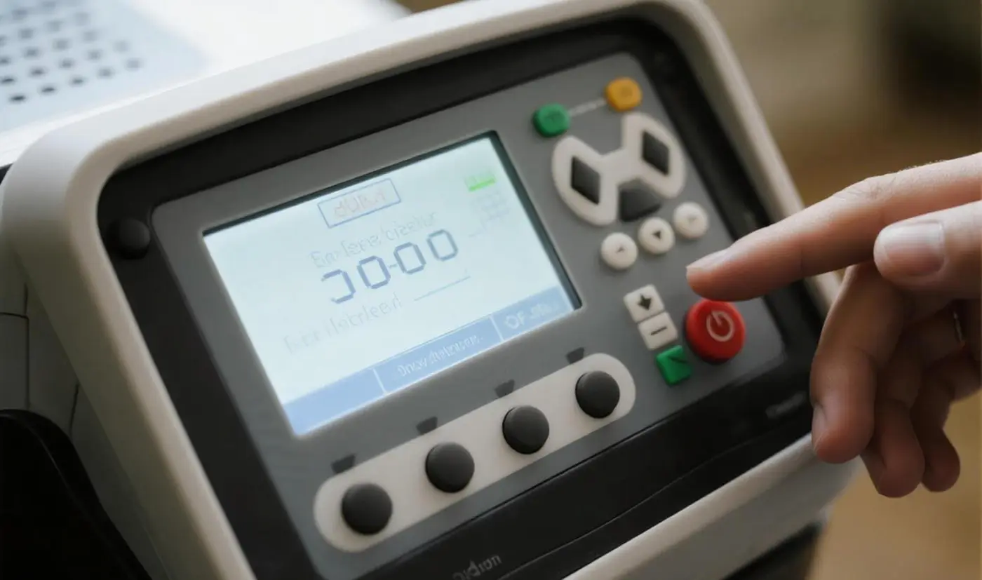
An operator in a cab does not read a panel; they find it. In a dusty cab, with the machine idling, the hand goes to a key by position and by feel before the eye confirms it. That is why the raised locator ring around a critical key earns its place in the drawing, and why a flat panel with identical keys separated only by silk-screened labels is a design that works in the showroom and fails in the field.
The second read is the light. A backlit legend under direct sunlight and under cab lighting should be tested at the same time, because a legend that reads well in a dark workshop can wash out at noon. The criterion worth writing into the drawing is contrast between the lit legend and the surrounding key face, not brightness in isolation.
Specifying a silicone panel keypad for a construction cab
The requirements that decide whether a cab panel survives are rarely exotic. They are ordinary conditions stated precisely: a temperature range with a cold-start figure, a cleaning method, an oil exposure, and the glove the operator wears. Each of those maps onto a moulding and a material choice rather than onto a feature list.
A panel that must be hosed down needs a continuous sealing lip and a gasket route that does not rely on adhesive alone; a panel cleaned with a dry brush needs abrasion resistance on the legend. A panel pressed with a heavy glove needs a larger key face and a shorter travel, not a harder rubber. Getting these three decisions right accounts for most of the field reliability difference between two panels that look identical in a photograph.

Where the numbers on a panel drawing come from
Force, travel and contact resistance are the three figures a panel drawing should carry, and each has a defined way of being measured. Peak force is read from a force-displacement curve taken on the assembled panel, not on a bare key. Travel is measured to the point the contact closes, which is not the same as the point the key bottoms out. Contact resistance is measured at end of life, after the specified cycle count, because the first-cycle figure is optimistic by construction.
If a supplier quotes these figures without saying how they were measured, the numbers are decorative. The measurement method is the part that transfers between projects; the value only transfers within one geometry and one material.
Questions buyers ask about construction machinery panel keypads
Can the keypad itself detect how hard a key was pressed?
Not on its own. A two-stage web or a dome with a second break produces a distinct intermediate state, but reading that state needs a controller that can resolve it. The keypad supplies the mechanical transition; the sensing is on the board.
Is a flat panel with printed legends acceptable in a cab?
It can be, if the keys are separated by moulded geometry rather than by print alone and the legend system is chosen for the cleaning method. Where operators work by feel, a raised locator on the two or three critical keys is worth more than extra printing.
Should the display window be moulded into the panel?
Usually yes for a sealed cab panel, because a moulded window removes a separate gasket route and one assembly step. It also fixes the window's optical flatness and coating at the moulding stage, which is easier to control than a bonded window over a large area.
This article describes the division of function between a moulded silicone front face and the electronics behind it. It does not assert ingress, cycle or temperature figures for any specific panel; those are set by the drawing, the material grade and the test protocol agreed for the part, and should be confirmed against the first-article report.
To review a cab panel, send the front-face drawing, the housing material and tolerance, the cleaning agents, the glove used and the annual volume with a peak month through the custom silicone quotation route. Panels that combine keys with a display opening are usually built as a custom silicone control panel, and the route from drawing to first article is set out on the custom silicone production process page.