Control Room Silicone Keypads and Operator Use Frequency
- Share
- Issue Time
- Sep 8,2026
Summary
Control room keypads wear unevenly because use is not uniform. Force drift, legend wear, and contact resistance on high-use keys - and how to design for the actual cycle count.
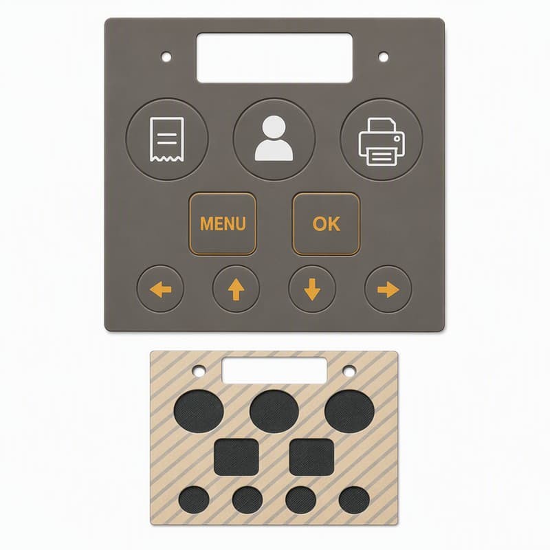
In a control room, the same three keys get pressed four hundred times a shift. After a year, they feel different from the keys nobody touches. The operator notices before the spec sheet does. High-frequency use is not a durability number on a datasheet — it is a wear pattern, and it has to be designed for, because the keys that fail are never the ones the cycle test pressed evenly.
The wear pattern: which keys fail first
The first thing to understand about control room keypads is that use is not uniform. A SCADA operator presses ACK, ENTER, and the arrow keys constantly; the CONFIG key gets pressed once a quarter. After a year, the high-use keys have seen half a million presses and the low-use keys have seen a few hundred. The pad was specified for one million cycles, and every key is under that number — but the high-use keys already feel different. The cycle life number is an average, and averages do not describe a control room.
Force drift over cycles
As a key is pressed repeatedly, the web ring fatigues. The storage modulus drops slightly, the web takes a small permanent set, and the peak actuation force falls. The snap ratio — the difference between peak force and return force, divided by peak — collapses first. A key that started at 140 g with a 50% snap ratio can drift to 110 g with a 25% snap ratio after several hundred thousand cycles. The operator does not measure this; the operator says "this key went soft."
The fix is not to specify a higher cycle number. It is to design the web and dome so the snap ratio stays above 40% at the expected cycle count, and to verify that with a cycle test followed by a force-travel measurement, not just a "still works" check [1].
Legend wear on high-use keys
The legend on a high-use key wears before the legend on a low-use key, and the wear mechanism depends on how the legend was made. Screen-printed legends wear from abrasion: the operator's finger rubs the ink, and after enough presses the ink thins and the legend fades. Laser-etched legends do not wear from abrasion because the character is part of the material stack, but they can degrade if the topcoat is attacked by cleaning chemicals. For a control room where keys are pressed constantly and the panel is wiped nightly, laser etching with a durable topcoat is the honest choice; screen printing is a cost decision that shows up as faded legends within a year [2].
Contact resistance drift
Under each key is a conductive pill — usually carbon — that closes a circuit on the PCB. As the key is pressed, the pill compresses and the contact resistance stays low. Over cycles, two things happen: the pill material compresses and takes a set, reducing contact pressure, and the carbon particles wear slightly, raising contact resistance. The result is a key that still clicks but occasionally does not register — the intermittent key that drives operators crazy and that incoming inspection never catches because it tests at zero cycles.
The target for initial contact resistance is typically below 500 Ω, with a lifetime target below 1 kΩ after one million cycles for carbon pills [3]. Specify both numbers, and test contact resistance after the cycle test, not before. The keypad maker does not build the PCB, but the contact resistance target has to be agreed with the PCB designer because the board's trace geometry and gold plating affect the measured value.
Cycle life standards and what they actually mean
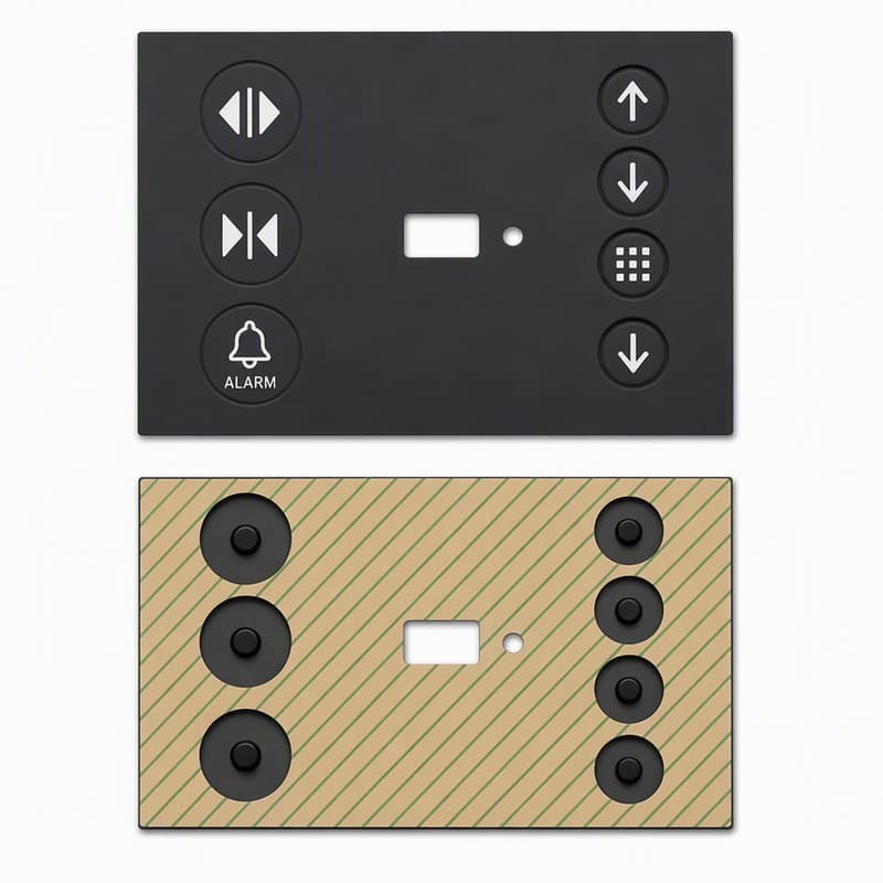
A keypad datasheet that says "one million cycles" is describing a lab test: a single key, pressed straight down, at a controlled rate, in a room-temperature environment, with no cleaning, no glove, and no temperature swing. A control room key is pressed at an angle, by a gloved hand, after a cleaning wipe, in a room that swings with the HVAC. The lab number is a ceiling, not a floor, and the difference between the lab and the control room is where the wear happens. Treat the cycle number as a starting point for a discussion, not as a guarantee.
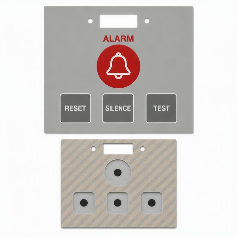
Case — a SCADA control room keypad and the uneven wear
A utility control room installed new SCADA panels with silicone keypads. Six months in, operators complained that the ACK and ENTER keys "felt dead" and occasionally missed a press. The panel had passed incoming inspection with flying colors — every key measured within spec at zero cycles. We pulled a used panel and measured the force-travel curves: ACK and ENTER had dropped from 145 g to 112 g, and the snap ratio had fallen from 48% to 22%. Contact resistance on ACK had risen from 180 Ω to 950 Ω. The CONFIG key, pressed twice a month, measured identical to a new part.
The fix was three changes. We thickened the web on the high-use keys from 0.4 mm to 0.55 mm to slow fatigue, switched the legends from screen print to laser etch, and specified a higher-density carbon pill with a post-cycle contact resistance target of 800 Ω. The revised panels have been in the same control room for eighteen months, and the ACK key still snaps. The lesson was that a control room keypad is not a uniform-cycle device — it is a set of keys with very different lives, and the high-use ones have to be designed for their actual cycle count.
Design rules for high-frequency control room use
- Map the actual use frequency per key; design high-use keys for their cycle count, not the average.
- Specify post-cycle force-travel-snap (snap ratio above 40% at target cycles), not just initial feel.
- Use laser-etched legends on high-use keys; specify the cleaning agents the topcoat must survive.
- Specify initial and post-cycle contact resistance; agree the target with the PCB designer.
- Run a cycle test on the actual high-use keys, with gloves and cleaning wipes if that is the real use.
- Consider a slightly thicker web on high-use keys to slow fatigue drift.
FromRubber builds custom silicone keypads for control room and industrial HMI use, with per-key use-frequency mapping, post-cycle force-travel verification, laser-etched legends, and contact resistance targets agreed with the customer's PCB designer. We do not build the PCB — we build the pad that has to land on it, and we test the high-use keys at their actual cycle count, not the average. If a control room keypad is wearing unevenly, send us the use map and the used part — we will tell you which keys need a different design.
Sources and test references used in this article:
- Diamond HMI, Rubber Keypad Design Guide: actuation force 125–150 g, snap ratio 40–60% for tactile keypads; force-travel verification recommended after cycle testing.
- Laser-etching versus screen-printing legend durability for silicone keypads per surface treatment references (2024–2025); industrial convention: alcohol wipe 1000+ cycles and abrasion 10,000+ cycles for readable legends.
- Carbon pill contact resistance: initial below 500 Ω, lifetime below 1 kΩ after one million cycles (silicone keypad conductive pill references; ISO 1853 for resistivity measurement).