Why Conductive Pillar Resistance Varies Across Silicone Keypad Batches
- Share
- publisher
- Suey
- Issue Time
- Aug 28,2026
Summary
Why conductive pillar resistance varies across silicone keypad batches: carbon loading, mixing, cure state, and molding pressure, plus the SPC controls and acceptance windows that keep contact resistance stable.
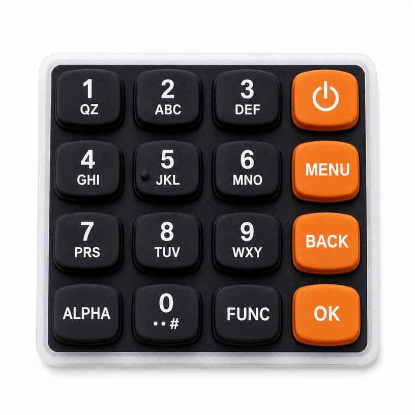
If you have ever qualified a silicone keypad for a handheld instrument and seen the same part number measure 45 Ω of conductive pillar resistance in one shipment and 90 Ω in the next, you already know the pain this article is about. Conductive pillar resistance is not a fixed property of a design — it is a process fingerprint. This guide explains the physical mechanisms behind batch-to-batch resistance variation in silicone keypad production, the process controls that keep it in check, and the acceptance criteria you should put in your next specification.
What Drives Conductive Pillar Resistance in a Silicone Keypad
A conductive pillar — often called a carbon pill or contact pill — is a small molded element on the underside of a silicone keypad dome. When the key is pressed, the pillar bridges two contact traces on the PCB and closes the circuit. The resistance of that pillar is determined by three layers of physics:
- Material conductivity: the ratio of conductive carbon black to silicone base polymer, and how evenly the carbon network is dispersed.
- Molded geometry: pillar height, diameter, and contact area against the PCB pad.
- Surface state: cure completeness, molding skin, and any release-agent residue on the contact face.
Commercial conductive pills are typically formulated around a blend of silicone rubber and conductive carbon black. A widely used formulation reference for silicone keypad contact pills is a 60% VMQ (methyl vinyl silicone) base with roughly 40% conductive carbon black, a ratio chosen to balance conductivity against the mechanical resilience the dome still needs. Above a certain carbon loading the conductivity rises sharply — the percolation threshold — which is exactly why small changes in compounding produce outsized resistance swings.
Why Contact Resistance Is Not "Just Contact Resistance"
In measurement instruments — clamp meters, thermometers, insulation testers — the keypad sits directly in the analog path or in the button-debounce logic that gates readings. A pillar that reads 40 Ω today and 160 Ω in a cold warehouse changes voltage-drop and noise margins. Instrument manufacturers who treat conductive pillar resistance as a cosmetic number often discover the hard way that it belongs in the same specification family as sensor tolerance and ADC reference accuracy.
Industry guidance on conductive contacts in rubber keypads notes that a well-controlled carbon contact maintains stable contact resistance over extended cycling — commonly cited at one million cycles — provided the compounding and cure are held constant. When that stability is lost, the first place to look is not the PCB, but the pillar itself.
Batch-to-Batch Variation: Where the Numbers Actually Come From
Every batch of conductive silicone starts from a compound recipe, and every recipe step is a chance to drift. The largest contributors to resistance spread across silicone keypad batches are:
1. Carbon masterbatch lot changes. Conductive carbon black is a commodity with lot-level resistivity variance. A new masterbatch lot with a 5% resistivity difference can shift pillar resistance by 20–40% because the compound sits near the percolation threshold.
2. Mixing time and shear. Under-mixing leaves carbon agglomerates; over-mixing can shear carbon chains and degrade the conductive network. Both produce measurable resistance differences between batches mixed on different days or by different operators.
3. Cure state. Partially cured silicone leaves a high-resistance skin on the pillar face. Cure time and temperature windows that are "close enough" for dimensional checks are often not close enough for resistance.
4. Mold surface and release agents. A contaminated or worn mold deposits release residue on the contact face, adding an insulating film that inflates resistance until it is worn through in the first thousand cycles.
None of these are visible in a visual inspection. Two batches can look identical, weigh identically, and still differ by a factor of two in pillar resistance — which is why the measurement, not the appearance, is the gate.
Root Causes of Resistance Drift Across Silicone Keypad Batches
When a customer reports resistance drift between batches, we follow a fixed investigation order that separates material problems from process problems:
- Re-measure under controlled conditions — fixed actuation force, fixed probe geometry, fixed temperature, because resistance is force- and temperature-sensitive.
- Check the compound certificate — confirm the carbon masterbatch lot and its resistivity range against the approved recipe.
- Section a pillar and inspect dispersion — agglomerates under magnification confirm an under-mixing or poor-dispersion cause.
- Verify cure state — durometer and specific-gravity checks catch partial cure that leaves a resistive skin.
- Run a 1,000-cycle preconditioning test — a resistive surface film wears through quickly; a genuine material problem does not.
Material-science references on carbon-black-filled silicone rubber confirm that the conductive filler content directly controls both electrical and mechanical behavior — higher carbon loading raises conductivity but also changes stiffness and elongation, so the compound engineer is always balancing conductivity against dome travel and snap ratio. That trade-off is why you cannot simply "add more carbon" to fix a resistance problem without breaking the tactile feel.
Rule of thumb: for a carbon-pill silicone keypad, specify conductive pillar resistance with both a nominal value and a batch acceptance window (for example nominal 50 Ω, accept 20–100 Ω at 150 gf actuation, 25 °C), and require the supplier to record the value per batch on the inspection report.
How We Control Conductive Pillar Resistance in Production
FromRubber controls conductive pillar resistance with the same discipline applied to dimensional tolerances. Every production lot is tested with a four-wire micro-ohmmeter at a fixed actuation force, and the values are plotted on an X-bar R chart. The process limits are derived from the approved sample, not from the spec sheet, which means the control chart catches drift months before it would violate a customer acceptance window.
- Compound lot traceability: every batch of pillars is traceable to the carbon masterbatch lot that produced it.
- First-article resistance measurement before the molding run is released.
- Periodic cross-checks of cured hardness (Shore A) to confirm cure-state consistency.
- Post-mold inspection of pillar faces for release-agent film under magnification.
Reading the Underside of the Keypad
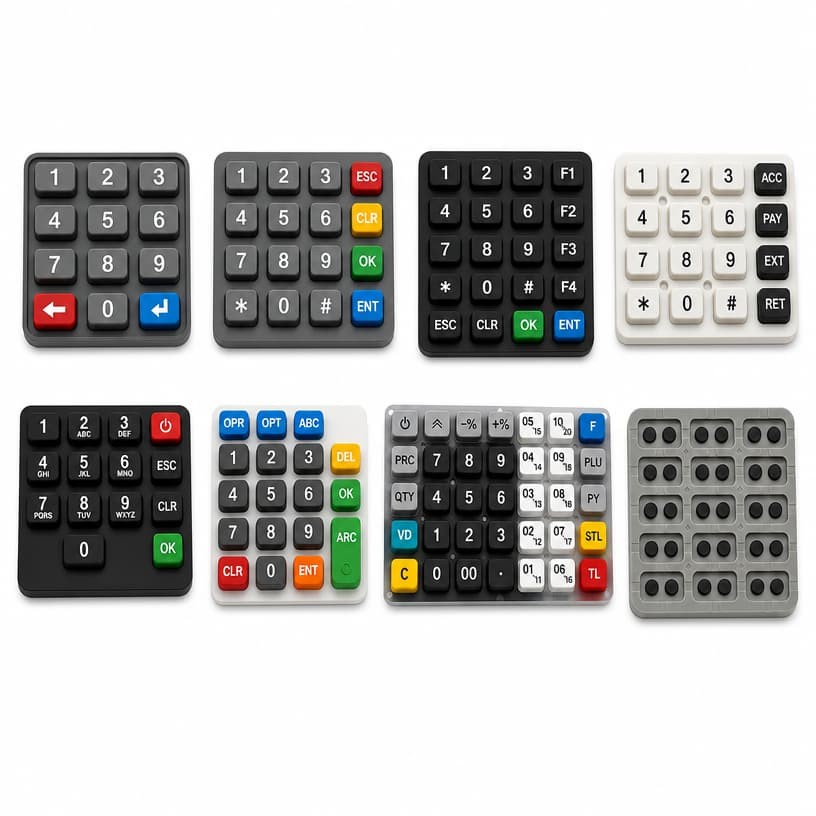
The underside of a silicone keypad tells the whole story. Each molded recess carries a conductive contact element, and the uniformity of those elements — size, height, surface finish — is the first physical evidence of process control. When you hold a new keypad sample, compare the pillars across the whole array: inconsistent pillar heights are the earliest predictor of inconsistent resistance, because contact area changes with every tenth of a millimeter.
For field-diagnosis guidance on reading resistance stability test reports and separating real drift from measurement artifacts, see our earlier article on how to read conductive carbon pill resistance stability test reports.
A Field Case: A 90 Ω Drift That Looked Like a Firmware Bug
A clamp-meter OEM shipped 12,000 units over six months with no complaint, then received a burst of RMA units reporting intermittent readings on the HOLD key. The firmware team spent three weeks chasing a debounce bug that did not exist. The actual sequence, reconstructed from batch records:
- Unit A (batch 04): pillar resistance 28–45 Ω. Button signal clean.
- Unit B (batch 11): pillar resistance 70–130 Ω at 0 °C. Marginal noise margin on the read line.
- Root cause: the molder switched carbon masterbatch lots without re-qualification, and the new lot shifted the compound closer to the percolation edge. Batch 11 also ran a shorter mix cycle to recover schedule time.
- Fix: mandatory masterbatch re-qualification, fixed mix-cycle SPC, and per-batch four-wire resistance recording with a hard acceptance window of 20–100 Ω.
The OEM's field failure rate returned to zero within two production cycles. The cost of the fix was a page of process controls; the cost of missing it was a full recall of a measurement product — a category where accuracy trust is the brand.
What This Means for Instrument Designers
If you specify a silicone keypad for any instrument where a button reading feeds a measurement, put conductive pillar resistance on the drawing and on the inspection plan. Pair it with the contact-resistance discussion in our guide on how contact resistance fluctuation can ruin measurement accuracy, and read the comparison of carbon pill versus conductive ink if you are still deciding between the two contact technologies.
Specifying Conductive Pillar Resistance for Your Next Silicone Keypad Order
A practical specification for conductive pillar resistance should contain five elements: a nominal value, an acceptance window, the test force and temperature, the measurement method (four-wire micro-ohmmeter), and the batch recording requirement. Add a preconditioning clause — for example 1,000 actuations before the acceptance measurement — so the value you approve is the value the customer experiences, not the value of an as-molded surface film.
Resistance drift between batches is a solvable problem, but only when it is specified, measured, and controlled. The references below document the material science and the industry practice behind the numbers discussed in this article.
Sources and further reading:
- Shin-Etsu — Contact Element for Keypads (material options for keypad contact elements)
- Grommet Seal — Carbon Pills: 60% VMQ and 40% Conductive Carbon Black (formulation reference)
- Rubber-Keypad — What Are Conductive Contacts in Rubber Keypads (contact stability and cycling)
- PMC — Effects of Carbon Black on Mechanical Properties of Silicone Rubber (filler loading trade-offs)
- Jasper Electronics — Conductive Rubber Keypads with Carbon Pills (application overview)
About FromRubber (FrmRubber). FromRubber is a full-process silicone and plastic OEM manufacturer specializing in custom silicone keypads for instrumentation, medical, and industrial equipment. We mold, print, and test under one roof, and every conductive pillar that leaves our factory carries a measured resistance value on its inspection record. If you are qualifying a new keypad or chasing a resistance problem on an existing product, send our engineering team your drawing — we will return a DFM review with the contact-resistance plan included.