Instrument Silicone Keypad Feels Either too Tight or too Loose in the Housing – Is the Dimension Wrong, or Is the Locating Groove Design off?
- Share
- publisher
- FromRubber
- Issue Time
- Sep 9,2026
Summary
A keypad that jams or rattles is rarely a single wrong dimension. Shrinkage compensation, measurement method, flash, groove draft and the tolerance stack between pad and housing decide the fit. Check the pair before redrawing.
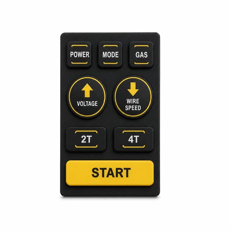
The instrument keypad either fights you into the housing or rattles inside it, and the first instinct is to blame the keypad dimension. But a silicone keypad does not have one dimension — it has a dimension that changed the moment it cooled out of the mold, a dimension the calipers cannot reliably measure, and a dimension that moves again when the housing heats up. Before you redraw the keypad, it is worth asking whether the locating groove and the tolerance stack are doing their job.
Why a "correct" keypad can still be the wrong size
Every molded silicone part shrinks as it cools from molding temperature to room temperature. Solid silicone (HCR) compounds commonly shrink in the range of roughly 1.5% to 3%, and liquid silicone rubber (LSR) is typically higher, around 2.5% to 4%, depending on compound and process. The shrinkage is not even: it varies with hardness, filler loading, wall thickness, and direction — parts shrink differently along the flow direction than across it, and a second post-cure step adds a little more. What this means in practice: a keypad drawing dimension is only realized after the tool cavity has been compensated for that specific compound's real shrinkage, and the compensation can only be confirmed by molding and measuring actual parts. If the cavity was cut with an assumed shrinkage that is off by even 0.2%, a 50 mm pad changes by a tenth of a millimeter — enough to turn a snug fit into a rattle.
There is a second, less obvious trap. Silicone is soft and viscoelastic: calipers squeeze the rubber and give a reading that depends on how hard the operator presses. Two inspectors can measure the same keypad and disagree by more than the tolerance they are checking. Measuring a soft part with a hard gauge is measuring the gauge's bite, not the part. Dimensional acceptance for keypads should use fixtures, optical measurement, or consistent low-force methods — and the method should be written down, because otherwise "the dimension was wrong" is often really "the measurement method changed."
Tight or loose is a stack, not a single part
"Tight" and "loose" are statements about the interface between two parts: the keypad's edge or locating rib, and the housing's groove. The keypad arrives with molding shrinkage and its own tolerance; the housing arrives with its own injection-molding tolerance; and the fit is the sum of both. A keypad that is 0.1 mm over its nominal and a groove that is 0.1 mm under theirs produce a 0.2 mm interference that can feel like a jam, while the opposite pair produces a rattle — with both parts individually "in spec." This is the tolerance stack, and it is the first thing to check when fit problems appear, because it explains how the same keypad can feel tight in one housing batch and loose in another.
The locating groove design that makes or breaks the fit
The groove does more than locate the pad — it controls how the pad is loaded when the housing closes, and how it survives demolding and assembly. Four design points decide most fit complaints:
- Draft angle. The groove walls and the pad's locating rib need draft so the pad enters without scraping, and so the molded rib can be released without tearing. Zero-draft grooves are a common cause of "hard to seat" complaints that get mislabeled as oversize parts.
- Groove depth vs. pad rib height. If the groove is shallow, the pad sits proud and the operator feels it; if the rib is short, the pad shifts. The two should be specified as a pair with a defined compression or clearance, not as independent dimensions.
- Edge geometry and flash. A thin molded flash along the pad edge — normal for compression-molded parts — can catch on the groove entrance and make the pad feel tight, even when the nominal dimensions are perfect. Flash control and trimming matter as much as the drawing.
- Uniform wall thickness. Thick and thin sections shrink differently, warping the pad's outline. A pad that is dimensionally right in the middle but warped at the edges will bind in the groove at the corners.
For key-to-bezel gaps around individual buttons, practical industry guidance for small silicone keys starts around 0.1 mm per side, rising to roughly 0.15–0.2 mm for larger keys over 20 mm, and it is generally kept below about 0.3 mm to avoid a loose feel and dust entry — but the right value depends on your housing's tolerance and the pad's shrinkage, which is exactly why the pair should be engineered together.
When the pad feels tight or loose, check in this order: (1) flash on the pad edge; (2) groove draft and depth against the drawing; (3) measurement method — was the pad measured with a fixture or a hand caliper; (4) housing tolerance — measure a sample of grooves, not one; (5) temperature at assembly and at use. More than half of "wrong size" complaints resolve before any drawing changes.
Temperature: the dimension that keeps moving
Silicone has a high coefficient of thermal expansion and its modulus drops sharply as it warms. A pad that is a comfortable interference fit at 20°C can become noticeably looser in a warm environment, and stiffer and harder to seat when the assembly line runs cold. "It fit in the summer and jams in winter" is a real phenomenon on rubber keypads, not a customer exaggeration. If your product crosses climates, the fit spec should state the temperature at which the assembly and the use fit are judged — the same temperature sensitivity discussed in our article on why industrial panel buttons feel different in winter.
How to settle the argument in one round
When the pad "must be the wrong size," ask for three pieces of evidence instead of arguing: the pad's measured outline at a documented temperature and method (fixture or optical); the housing groove's measured width and depth across several parts; and the assembly torque or force used when the operator felt the tightness. With those three, the problem identifies itself: oversized pad, undersized groove, flash, draft, or measurement error. If the supplier only responds with "our dimensions are per drawing," that is a measurement story, not a fit story — and fit is what you actually shipped.
One case: a welding machine pad that jams in cold assembly
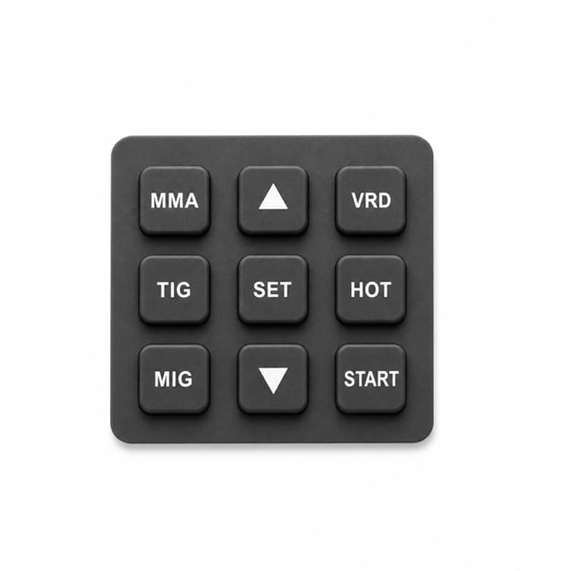
A customer's welding machine keypad was reported tight in the housing — hard to seat, and in a few units the edge of the pad pinched during assembly. The drawing said the pad and groove were both to spec. We measured with fixtures, not calipers: the pad outline was fine, but the housing groove had near-zero draft, and the pad's edge carried a thin molded flash that the compressed-molding process left behind. At the cold end of the assembly line, the rubber stiffened and the flash caught on the draftless groove wall. The fix was threefold: a small draft added to the groove, a flash-trimming step on the pad, and a documented 0.1 mm fit clearance recalculated for the compound's real shrinkage. The same pad drawing was used; no keypad dimension changed. The problem was the pair, not the part.
Putting the fit into the spec
Add a fit clause to your keypad spec: nominal outline, shrinkage allowance basis for the compound, measurement method and temperature, allowed edge flash, and the mating groove's draft and depth range. None of these are exotic requirements, but together they turn "it's tight" from an argument into a checklist. A supplier who can quote shrinkage for your specific compound, measure with fixtures, and document the pair's stack is a supplier who has already solved this problem before you asked.
Related reading
In short
A keypad that feels tight or loose is rarely a single wrong dimension. It is shrinkage compensation, measurement method, flash, groove draft, tolerance stack and temperature, all acting on one interface. Check the pair — pad and groove — with fixtures at a documented temperature, before you redraw anything. In most cases, the drawing was fine and the stack was not.
This article was written by the molding engineering team at FromRubber, a custom silicone keypad manufacturer in Dongguan, China. We set shrinkage allowances per compound, measure soft parts with fixtures, and verify the pad-and-groove pair with our customers before production.
Sources
- Silicone molding shrinkage: HCR roughly 1.5%-3%, and the ±0.05 mm practical precision limits of molded silicone. http://m.toutiao.com/group/7680013760430146058/
- LSR shrinkage range 2.5%-4% and anisotropic shrinkage between flow and cross-flow directions. http://m.yingtai168.com.cn/xinwen/bGAyX.html
- Rubber compression molding shrinkage typically 1.5%-3%, varying with hardness, filler and direction. https://m.sohu.com/a/1067733451_122906209/
- Keypad-to-housing gap guidance: about 0.1 mm per side for small keys, 0.15-0.2 mm for larger keys, with draft angle and uniform wall thickness. http://rubber9.com/wap/index.php?ac=article&at=read&did=674