Silicone Mold Parting Line Design: How to Control Flash
- Share
- publisher
- Suey
- Issue Time
- Jul 28,2026
Summary
Master silicone case mold parting line design. Learn precision techniques to eliminate flash, position parting surfaces correctly, and achieve flawless silicone protective cases with FromRubber engineering expertise.
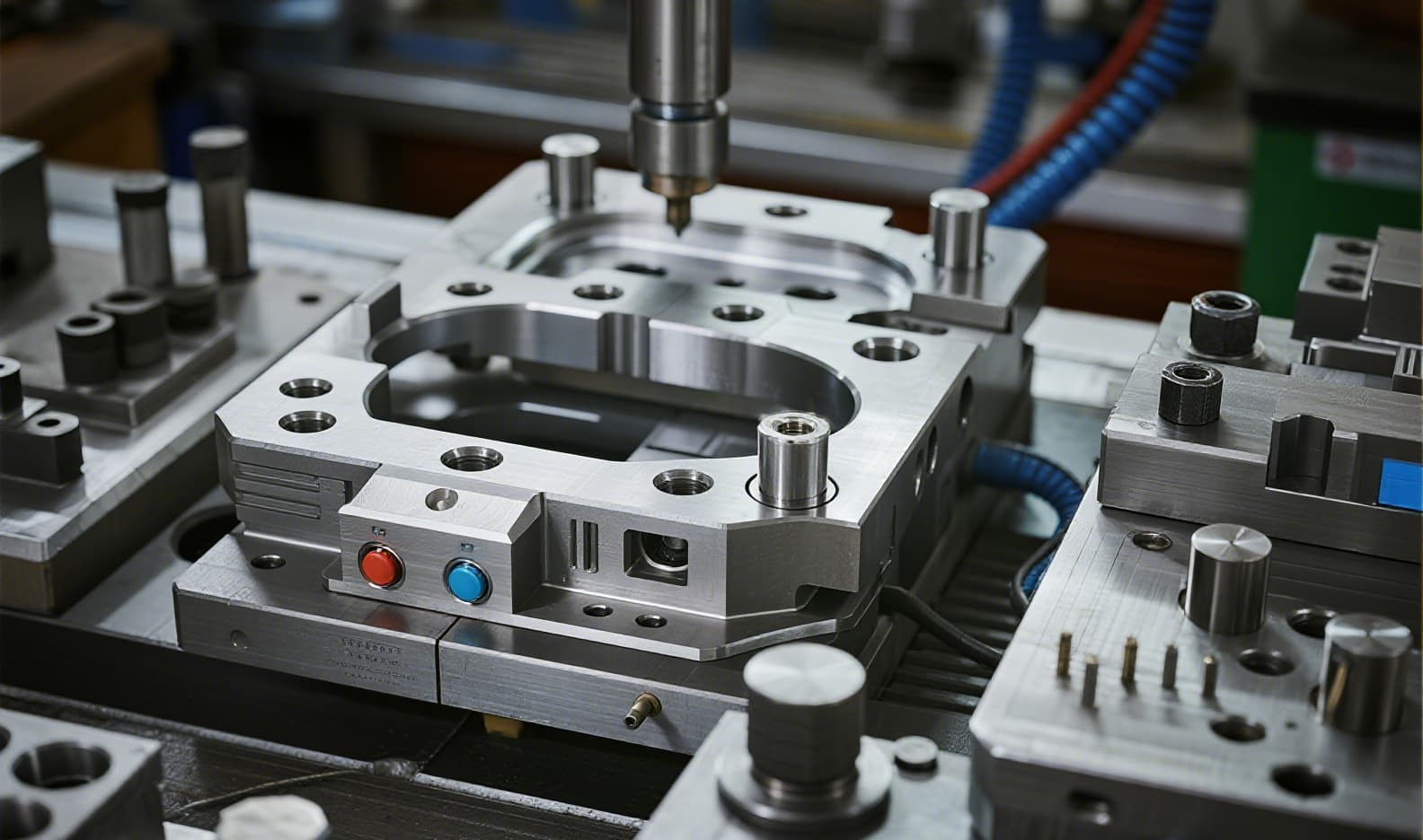
The parting line is one of the most important decisions in silicone mold design because it affects flash, cosmetic appearance, sealing performance, trimming requirements and production cost. For silicone cases, the best parting line is not simply the easiest line for the mold maker to manufacture — it should be positioned according to the product geometry, cosmetic surfaces, sealing areas, wall thickness, demolding direction and expected flash location. This guide explains how to select a silicone mold parting line, which locations should be avoided, why flash occurs, and how DFM and mold manufacturing decisions can reduce parting-line defects before mass production.
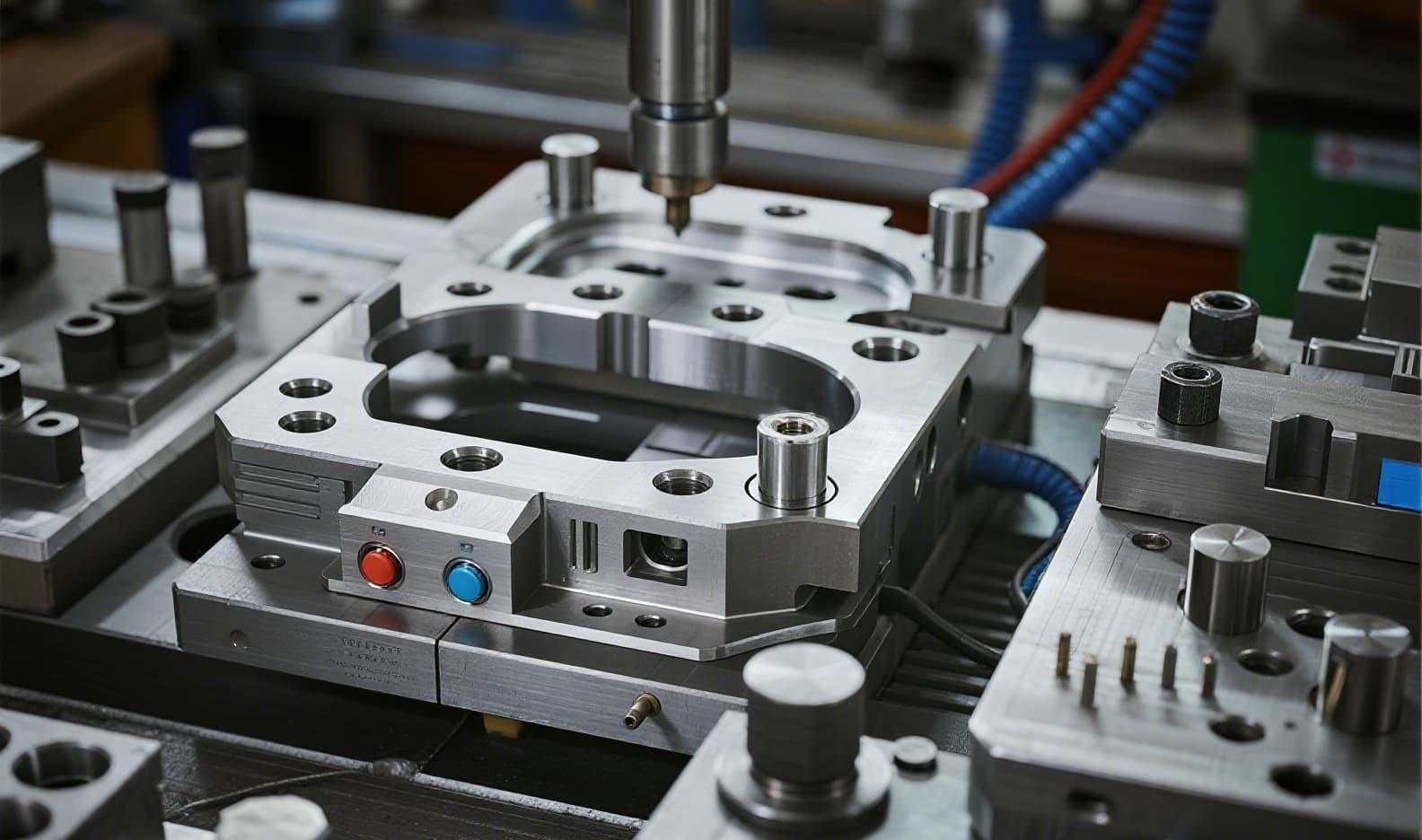
Precision mold parting surface under CNC inspection at FromRubber's facility.
What Is a Parting Line in Silicone Molding?
A mold parting line is the boundary where two or more mold sections meet to form a silicone component. The two mold halves are separated along this boundary so the cured silicone part can be removed. After molding, the boundary may appear on the part as a visible witness mark or as a thin film of excess material called flash, depending on mold design, material behavior and process conditions.
The parting surface is the actual flat or contoured area of the mold where the two halves seal against each other. Its accuracy — flatness, surface finish and shut-off — is what controls how much silicone can escape between the halves during molding.
Parting Line vs. Flash: What's the Difference?
A parting line is not necessarily a defect. Every two-part mold produces a parting line; the question is whether it is positioned discreetly and whether the material escaping along it stays within acceptable limits.
| Term | Meaning |
|---|---|
| Parting Line | The boundary created where mold sections meet; present on every molded part |
| Witness Mark | A visible line left on the molded part at the parting boundary — cosmetic, not structural |
| Flash | Excess silicone extending beyond the intended part geometry along the parting line |
| Deflashing | A secondary process used to remove excess material from the finished part |
A parting line is a design feature. Flash is material that has escaped the cavity and may require correction or secondary finishing. Good mold design does not eliminate the parting line — it controls where it sits and keeps flash within the acceptance limit.
Why Parting Line Location Matters
If you have ever received a silicone protective case with a rough edge that feels scratchy, or noticed a thin film of excess silicone along the seam, you have seen the result of poor parting line placement. The parting line is where the two halves of a mold meet, and on every silicone product it leaves either a subtle witness mark or visible flash. You cannot eliminate it — but you can choose exactly where it goes, and that choice determines the product's cosmetic quality, manufacturing yield and production cost.
For brand owners, procurement managers and industrial designers sourcing custom silicone case molds, parting line strategy is one of the most important checks before committing to tooling. A poorly placed parting line can trigger expensive T2 and T3 mold revisions, scrap thousands of parts, and delay product launch by weeks. A well-designed one produces a near-invisible seam, minimal post-processing and high yield. FromRubber has engineered over 1,200 custom silicone molds for electronics brands; the design rules below are the parting line philosophy used on production tooling, built on more than 15 years of silicone mold manufacturing.
Where Should the Parting Line Be Placed?
Best Locations for Silicone Cases
The golden rule of silicone case mold parting line design is simple: place the parting line where the user will never see or feel it. In practice this means positioning it along the natural geometric transitions of the product:
- Along the inner bottom fillet transition — the curve where the sidewall meets the base interior is naturally shadowed and out of sight
- Inside the edges of port openings and button cutouts — these functional openings already have defined edges that disguise the witness line
- Along natural transitions between sidewalls and bottom surfaces — any geometric break in the surface provides a camouflage zone
Areas to Avoid
- Across a flat, high-gloss cosmetic surface — flash and witness marks become highly visible
- Through sealing surfaces — flash on a sealing face causes functional failure
- Across embossed textures, logos or patterns — the parting line interrupts pattern continuity
During FromRubber's DFM review, the proposed parting line is marked directly on the customer's 3D model. Steel is never cut before the customer approves this single most consequential design decision. Request a silicone mold DFM review.
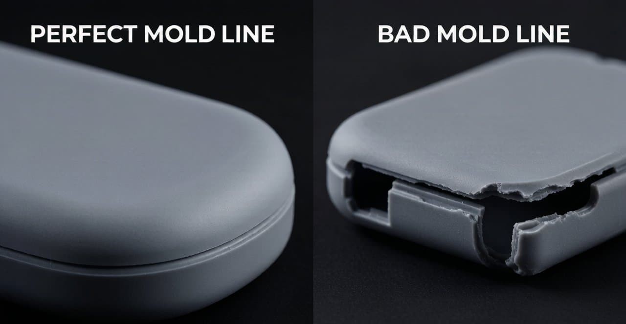
Good versus bad parting line placement on silicone protective cases (FromRubber QC comparison).
How Parting Line Design Affects Silicone Mold Flash
Common Causes of Flash
Flash is rarely a single-cause problem. It is almost always the result of interacting factors between the mold, the material and the process:
| Root Cause | Symptom | Typical Correction |
|---|---|---|
| Insufficient clamping force | Uniform flash around the entire parting surface | Increase tonnage; verify with clamp-force calculation |
| Worn or damaged parting surface | Localized flash in one area | Regrind surface; recheck flatness |
| Oversized vent grooves | Flash at vent locations only | Reduce vent depth to the designed range |
| Low-viscosity or over-flowing material | Extremely thin, widespread flash | Select a suitable grade; control mold temperature |
| Excessive mold temperature | Flash worsens as temperature rises | Stabilize at the optimal cure temperature |
How to Reduce Flash
FromRubber applies a three-layer flash-control protocol on production molds:
- Design geometry that minimizes flash impact — parting line placement and overflow groove design are decided before tooling
- Precision tooling with tight shut-off — controlled parting surface accuracy keeps the escape path minimal
- In-process inspection — catch deviation before scrap accumulates, not after
How Much Flash Is Acceptable on a Silicone Part?
Acceptable flash depends on the part's function and cosmetic standard, not on a universal number. The acceptance criteria should be agreed in the DFM phase and stated on the drawing:
- Visible cosmetic surfaces — flash must be below the visible threshold; on premium cases FromRubber targets flash of 0.03 mm or less with measurement taken along the parting line
- Functional or sealing areas — zero flash is typically required because any excess breaks the seal
- Interior, non-visible areas — small flash may be acceptable if it does not interfere with fit
Specify the acceptance limit on the drawing and verify it by measurement — a flash limit that is never measured is not a specification. The practical route is to agree the limit during DFM, confirm it on the first article, and keep the same criterion through production.
Silicone Mold Parting Surface Design
Parting Surface Flatness
The accuracy of the parting surface directly determines flash thickness. For precision silicone molds, a controlled and consistent parting surface is critical to minimizing flash. The target tolerance should be established according to the product geometry, material and required cosmetic standard. As a production reference, FromRubber holds flatness on the parting surface to 0.01 mm or better across the surface, verified on a CMM or with a straightedge and feeler gauge, and checks contact with a Prussian blue transfer test on trial runs.
Shut-Off Design
Shut-off is the sealing geometry where the two mold halves meet. A proper shut-off balances flash control against venting — too tight a shut-off starves air escape, too loose a shut-off allows flash. The shut-off width and clearance are designed for the specific silicone grade and cavity pressure.
Venting
Trapped air in the cavity causes short fills and burn marks; the vent must let air escape without letting silicone out. Vent depth is typically held well below the flash threshold for the material — shallow enough to pass air, deep enough to avoid blocking. Vent locations are confirmed during mold flow simulation rather than discovered on the press.
DFM for Silicone Mold Parting Line Design
DFM is where parting line decisions are actually made. Before any steel is cut, the design is reviewed for draft angle, wall thickness, undercuts, demolding direction, and where flash will appear if the process drifts. A DFM review that marks the parting line on the 3D model prevents the most expensive errors: parting lines placed on visible surfaces, across seals, or through textured areas.
How to Choose the Parting Line Before Making the Mold
- Identify cosmetic surfaces — surfaces the end user sees and touches daily
- Identify sealing areas — faces that must seal against a housing or another part
- Determine demolding direction — the direction the part leaves the mold constrains where the line can sit
- Identify undercuts — features that lock the part in the mold force the line around them
- Evaluate wall thickness — thin walls flex during demolding and shift flash behavior
- Determine venting locations — vents are placed where air traps, which is often where flash risk concentrates
- Predict flash risk — compare the candidate line against the cause table above
- Confirm the parting line on the 3D model — freeze it in DFM before tooling starts
The parting line should be approved during DFM before mold manufacturing begins. This single step separates a project that ships on time from one that burns a T2 revision.
Case Study: Reducing Silicone Case Flash from 0.15 mm to 0.03 mm
A leading audio brand brought FromRubber a Bluetooth earbuds charging case cover with the original parting line running through the middle of the front sidewall. The result was a 15% rejection rate and rising customer complaints.
Customer Problem
15% of units required manual flash trimming, adding labor cost per unit. Hand-trimmed cases had inconsistent edge quality — some under-trimmed (still scratchy), others over-trimmed (thin wall, loose fit).
Root Cause
The original parting line crossed the visible sidewall, placing flash directly in the user's sightline and touch zone.
Engineering Solution
- Relocated the parting line from the visible sidewall to the inner R-angle at the base — hidden from the user's view
- Improved the parting surface, reducing the surface gap to a controlled value by precision re-grinding
- Added an overflow groove adjacent to the parting line to trap minimal flash
- Added cryogenic deflashing as a secondary pass — no hand labor
Result
| Metric | Before | After |
|---|---|---|
| Flash | 0.15 mm | 0.03 mm |
| Yield | 85% | 98% |
| Manual trimming | Required | Eliminated |
| Labor cost | +$0.32 / unit | Eliminated |
The redesign eliminated the manual trimming step entirely, cut flash below the visible threshold, and removed a major source of quality variation. Case figures are taken from FromRubber's production records for this project.
Silicone Mold Flash Removal Methods
Even with optimal parting line placement, some products — particularly ultra-thin cases under 0.6 mm wall thickness — may require post-molding finishing. FromRubber uses a graded approach to secondary operations:
| Method | Flash Removed | Best For |
|---|---|---|
| Cryogenic deflashing | Thin, brittle flash | High-volume thin silicone cases |
| Manual inspection + micro-trim | Any remaining flash | Low-volume premium samples, first articles |
| No finishing needed | None (flash within limit) | Production-optimized molds with precision parting surfaces |
The goal is always to eliminate post-processing by getting the parting line right in the DFM phase. Production data at FromRubber shows the majority of new silicone case molds produce parts within the flash limit on the first trial, requiring zero secondary finishing.
How We Validate Parting Line Design Before Mold Production
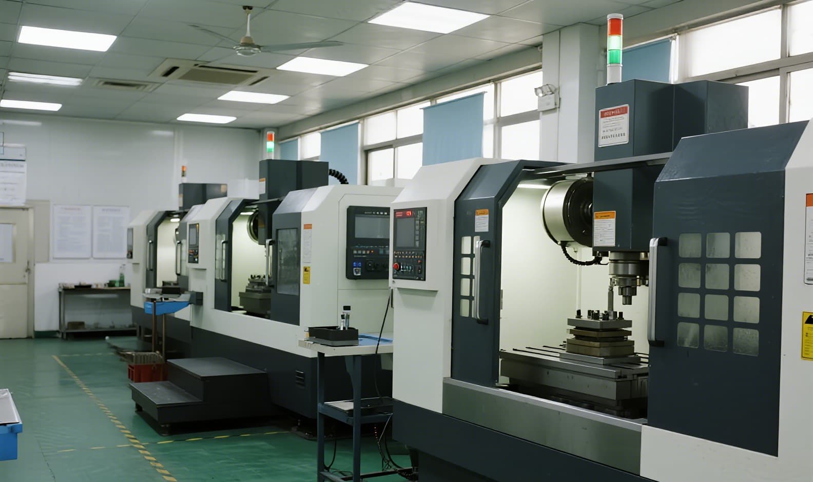
FromRubber's in-house mold workshop: CNC machining, EDM and assembly under one roof.
Parting line quality is validated before production, not discovered during it:
- Mold flow simulation — filling pattern, weld lines, air traps and pressure distribution at the parting line are reviewed before steel is cut; simulation reveals whether uneven pressure will make the mold breathe and produce flash
- CNC and EDM accuracy — mold halves are cut on high-speed CNC or mirror EDM equipment, then flatness and contact are verified on the assembled tool
- Prussian blue contact test — dye is applied to one half, the mold is closed under pressure, and the transfer pattern is inspected; uniform coverage means good contact, patchy transfer means high spots need correction
- First-article dimensional report — CMM and 3D blue-light scanning confirm the part matches the drawing before mass production sign-off, with process capability reviewed on critical dimensions
How to Choose a Silicone Mold Manufacturer
The quality of a silicone part's parting line ultimately reflects the capability of the mold manufacturer. When evaluating a custom silicone mold manufacturing partner, check for:
- In-house tooling — a manufacturer that designs and cuts its own molds controls the entire tolerance chain; outsourced tooling adds communication gaps
- CNC and EDM capability — high-speed CNC and mirror EDM are prerequisites for flat parting surfaces
- DFM as a standard service — a free DFM analysis with the parting line marked on the 3D model before tooling commitment
- Integrated silicone molding — tooling and production under one roof so trial-run issues are corrected without cross-vendor coordination
- Quality system certification — ISO 9001 / IATF 16949 certification shows equipment calibration, material traceability and process control are documented
FromRubber checks all five boxes: 15+ years of precision silicone molding, in-house mold workshop, and over 1,200 custom silicone molds delivered to electronics brands. See our custom silicone rubber parts and custom silicone products pages for the production range.
Ready to Engineer Your Silicone Case Mold?
Get a free DFM analysis with a parting line recommendation. Send your 3D model and we will show you how to achieve a clean finish without flash problems.
Send Your Design for Free DFM ReviewFAQ
What is a parting line in silicone molding?
A parting line is the boundary where two or more mold sections meet to form a silicone component. After molding it may appear as a visible witness mark or as thin flash, depending on mold design, material and process conditions.
Where should the parting line be placed on a silicone case?
Along natural geometric transitions where the user cannot see or feel it: the inner bottom fillet, inside edges of openings, and transitions between sidewalls and bottom surfaces. Avoid flat cosmetic surfaces, sealing faces and textured or logo areas.
Can a silicone mold have an invisible parting line?
No mold can remove the parting line entirely, but it can be positioned so the witness mark falls on a shadowed or geometrically broken surface where it is effectively invisible to the user.
What causes flash on silicone molded parts?
Flash is caused by silicone escaping between the mold halves. Common contributors are insufficient clamping force, worn or damaged parting surfaces, oversized vents, excessive material flow, and high mold temperature.
How do you reduce flash on silicone parts?
Reduce flash at the design stage: place the parting line discreetly, keep the parting surface flat and consistent, control vent depth, and stabilize process temperature. Where needed, add an overflow groove or a secondary deflashing step.
How much flash is acceptable on a silicone product?
It depends on the part's function and cosmetic standard. Visible surfaces need flash below the visible threshold; sealing surfaces typically require zero flash. The acceptance limit should be agreed in DFM, written on the drawing and verified by measurement.
Can the parting line affect sealing performance?
Yes. A parting line through a sealing face produces flash that breaks the seal, and any witness mark on a seal surface can create a leak path. Sealing faces should be kept clear of the parting line.
Should the parting line be reviewed before mold manufacturing?
Yes — this is the single most important DFM step. Once steel is cut, moving the parting line means a T2 revision. Reviewing and approving the line on the 3D model before tooling saves time, cost and scrap.
What is DFM in silicone mold design?
DFM (Design for Manufacturing) is the review of a product design for manufacturability before tooling: draft, wall thickness, undercuts, demolding, parting line location and predicted flash are checked so the mold is built right the first time.
How can I send my silicone case design for DFM review?
Send your 3D model through the quotation form. FromRubber returns a free DFM analysis with the recommended parting line marked on the model, typically within three business days of receiving the file.