Is Your Silicone Keypad Design Fighting Against the Handheld Meter Housing?
- Share
- publisher
- Suey
- Issue Time
- Aug 25,2026
Summary
Silicone keypad and handheld meter housing co-design: fit clearances, tolerance stacks, sealing, mounting holes and thermal expansion - the DFM rules that prevent conflicts.
Design for Manufacturing
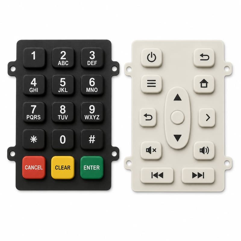
The silicone keypad and the handheld meter housing are designed by different people, on different schedules, sometimes in different companies. When the two halves meet at assembly, the conflict surfaces: the keypad bulges, the gasket line leaks, the keys bind against the bezel, or the pad floats loose inside the pocket. Almost all of these fights are preventable - the rules are known, and the cost of following them is a DFM review that takes an afternoon instead of a tooling revision that takes months.
1. Why Handheld Meter Housing and Silicone Keypad Designs Conflict
The most common source of keypad-housing conflict is a mismatch of expectations about the silicone part's behavior. Injection-molded plastic is rigid and holds tight tolerances; a molded silicone keypad is a soft, flexible elastomer that shrinks after molding, compresses under load and expands with temperature. When the housing designer leaves a "standard" 0.1 mm gap and the keypad designer assumes 0.3 mm of clearance, the result is keys that bind, or a pad that rattles. Both designs can be correct in isolation and wrong together.
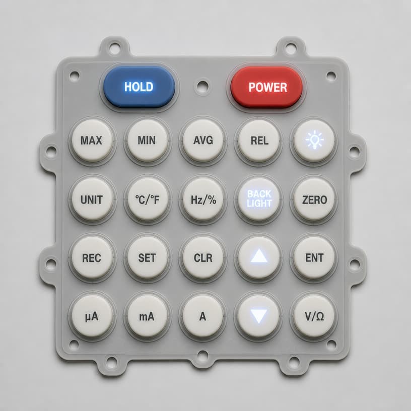
The fix is a shared drawing review against a small set of integration rules before either part is finalized. The rules cover four areas: fit clearance, tolerance stacking, sealing and mounting, and thermal expansion. The seven DFM rules for integrated keypad and enclosure design give the complete list; this article walks through the four that most often break handheld meters.
2. Fit Clearance and Tolerance Stacks in Handheld Meter Keypad Design
Fit clearance is the gap between the key cap and the housing opening through which it protrudes. Too small, and the key binds on the bezel - especially after the housing is painted or the keypad swells in humidity. Too large, and the key wobbles and lets dust in. The honest engineering range for instrument keypads is roughly 0.2–0.4 mm per side, and the number must be chosen against the real tolerance stack: housing mold tolerance, keypad shrinkage variation, and assembly tolerances all add up.
The classic failure is the "0.1 mm gap" assumption. A 0.1 mm clearance that looks generous in CAD disappears when the housing mold runs +0.05 mm and the keypad runs +0.05 mm and the paint adds another 0.03 mm - the key now drags. Our guide to the overlooked 0.1 mm gap clearance explains exactly this mechanism, and the complete fit clearance guide provides the calculation method with worked examples.
The rule: specify the clearance at the worst-case corner of the tolerance stack, not at nominal. If the stack says 0.35 mm worst case, design for 0.35, not 0.1.
3. Sealing, Mounting Holes and the Integration of Silicone Keypad with Housing
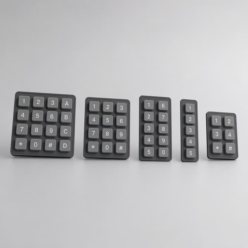
Handheld meters sold for outdoor or industrial use carry IP ratings, and the keypad is often part of the sealing system. Two sealing architectures exist: a perimeter gasket molded onto the keypad base that compresses against a housing rib, or an overmolded seal that the housing clamps. Each demands specific housing features - a continuous compression rib with the right height and hardness, generous radii, and no parting lines crossing the seal path.
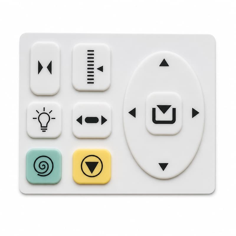
Mounting holes look trivial and cause real trouble. Holes must align with the housing boss pattern within the silicone shrinkage tolerance; a 0.3 mm mismatch at one corner produces a visible bulge and a broken seal. The locating-hole scheme matters even more: without a positive locating feature (pin holes or edge registration), the pad drifts during assembly and the legend grid shifts relative to the bezel - a cosmetic defect that reads as "cheap product" to the end user.
For sealed designs, our IP67/IP68 keypad sealing guide covers gasket geometry, compression ratios and housing rib design with test data.
4. Thermal Expansion: The Physics Most Handheld Meter Designers Skip
Silicone elastomer expands roughly ten times more than the plastic housing over temperature. A keypad that fits perfectly at 23°C can develop visible buckles at 60°C and bind at −20°C. The numbers are small - a 60 mm keypad grows about 0.3–0.4 mm over a 40°C swing - but that is exactly the size of the clearance you may have "saved" by designing tight. The result is temperature-dependent feel: crisp in the lab, sluggish in the sun.
Three mitigations are standard in instrument design. First, anchor the keypad at its center and let the edges float, so expansion is distributed instead of accumulated at one corner. Second, size the clearance for the worst-case hot condition, not the drawing temperature. Third, test the assembled unit over the full temperature range - a functional check at 23°C tells you nothing about the desert or the freezer.
Also plan the escape clearance under the pad: a sealed pad needs space for air to move when pressed, or it acts like a suction cup. The escape clearance design guide shows why a bottomed-out pad punctures and how to prevent it.
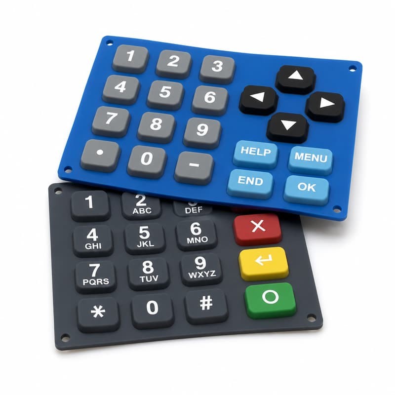
5. Case Study: A Keypad-Housing Conflict Fixed at DFM Review
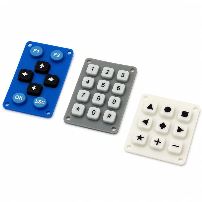
A handheld moisture meter was ready for tooling when the DFM review caught a conflict: the housing designer had specified a 0.15 mm key clearance, and the keypad supplier had assumed 0.30 mm in the pad drawing. Neither was wrong on paper; together they guaranteed binding keys on a quarter of production units and a seal that wept water at the IP65 test.
FromRubber's DFM review resolved it in one session: the clearance moved to 0.25 mm nominal with the housing draft adjusted, the keypad's locating pins were added at the center line, and the gasket rib height was raised by 0.15 mm to restore the compression ratio. Tooling had not been cut, so the total cost was a drawing revision. The meter passed IP65 on the first sealed-unit test and has shipped without keypad-related returns for two years.
6. DFM Rules for Silicone Keypad and Handheld Meter Housing Co-Design
Review the fit clearance at the worst-case tolerance corner, not nominal
Add positive locating features (pin holes / edge registration) to the keypad
Design sealing features as a system: rib height, hardness and compression ratio together
Anchor the keypad at center; let edges float for thermal expansion
Verify function across the full temperature range, not just at 23°C
Plan escape clearance so the pad cannot bottom out on the PCB
Sources and Further Reading
Engineering background draws on published material from Xometry - liquid silicone rubber molding design guide, Diamond HMI - rubber keypad resources, and Google Patents - silicone keypad and enclosure designs. Fit and sealing figures reflect FromRubber DFM records for instrument programs.
Get a DFM Review Before You Cut Tooling
FromRubber reviews keypad and housing drawings together, returns a conflict list with recommended fixes, and supports the design through tooling and validation.
About FromRubber - FromRubber is a full-process silicone keypad manufacturer for handheld instruments and industrial electronics, offering DFM review, mold making, molding, printing, backlighting and testing in one facility.