Why Rubber Keypad Tooling Choices Haunt Handheld Meter Production Later
- Share
- publisher
- Suey
- Issue Time
- Aug 25,2026
Summary
Rubber keypad tooling for handheld meters: mold steel, cavity count, parting lines and tooling validation - decisions made early that determine yield and cost later.
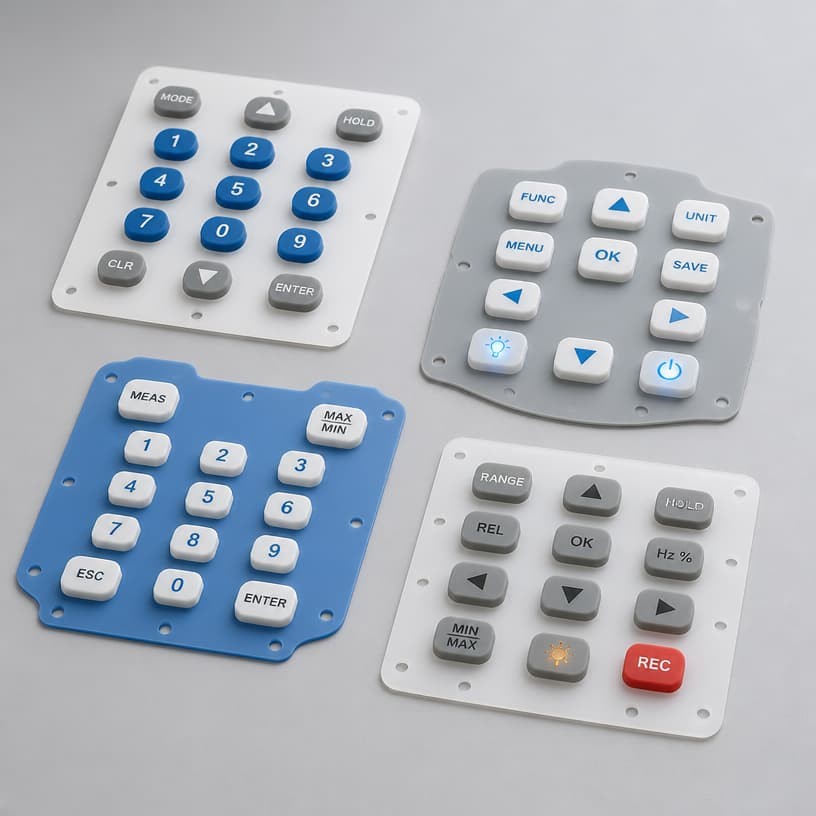
Tooling Strategy
Every handheld meter production program starts with the same quiet decision: how much mold to buy, in what steel, with how many cavities. The choice looks like a line item in a quotation - and it comes back five years later as yield problems, repair rates and endless deflashing hours. Rubber keypad tooling is the least reversible decision in the program, because the mold is the product. This article explains the tooling choices that haunt handheld meter production, and the ones that keep it running smoothly.
1. How Rubber Keypad Tooling Decisions Echo Through Handheld Meter Production
The mold for a rubber keypad defines every dimension the keypad will ever have: key pitch, pad height, dome thickness, legend registration, parting line position. Once the mold is cut, correcting a mistake means a new mold - weeks of lead time and thousands of dollars. Yet tooling decisions are often made on price alone, with three variables ignored: steel grade, cavity count and parting line strategy. Each one has a predictable, delayed consequence in production.
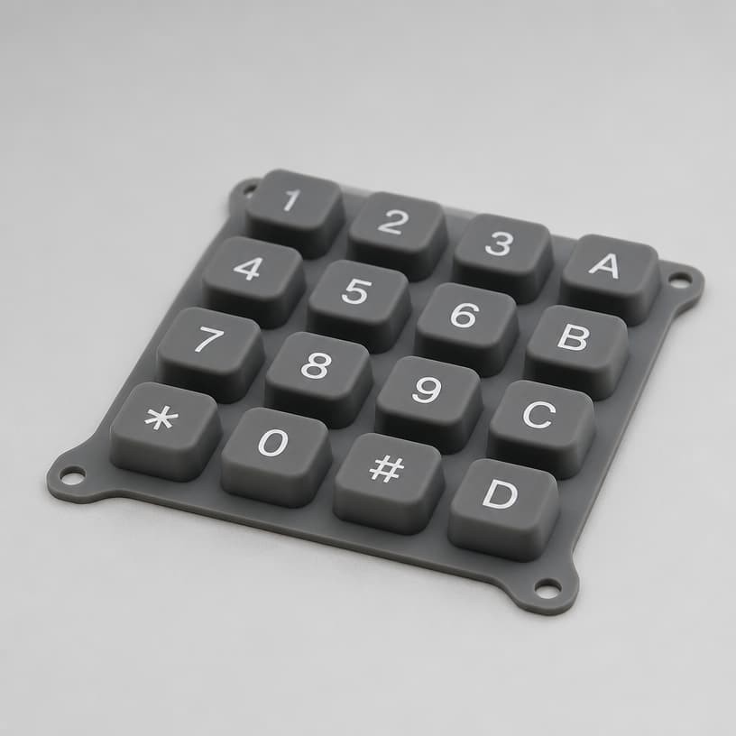
A cheap mold in soft steel may quote 30% less than the right one, and it will deliver that saving back as problems: parting line wear that grows flash, cavity corrosion that roughens the key surface, and dimensional drift that pushes keypads out of tolerance after a few hundred thousand cycles of molding. For a handheld meter expected to run for years, the tooling cost is spread over the whole program - and the wrong steel changes the per-unit cost more than the mold price ever did.
2. Mold Steel and Mold Life for Handheld Meter Rubber Keypads
Keypad molds are typically cut in pre-hardened tool steel (P20/718 grade) or hardened steel (H13/S136), with mirror-polished cavity surfaces where the key caps demand a glossy finish. The steel choice sets two things: mold life and surface consistency. Hardened grades resist wear and hold the polished finish longer, which matters for keypads with high-gloss surfaces - the finish is molded, not applied. Our mold steel selection guide documents a case where the wrong steel shortened mold life tenfold; the cost difference between the right and wrong steel is small compared to the cost of replacing the mold mid-program.
Surface finish deserves its own specification line. A glossy key cap needs a mirror cavity (RA 0.05–0.1 µm) achieved by diamond polishing or a mirror-finished insert; a matte cap needs a fine etching that must be uniform across every cavity. Both finishes are decided at tooling and are nearly impossible to change economically afterward. The mirror-vs-coating trade-off for glossy keypads is analyzed in our mirror mold vs coating comparison.
3. Parting Lines, Flash and Cavity Count in Keypad Tooling
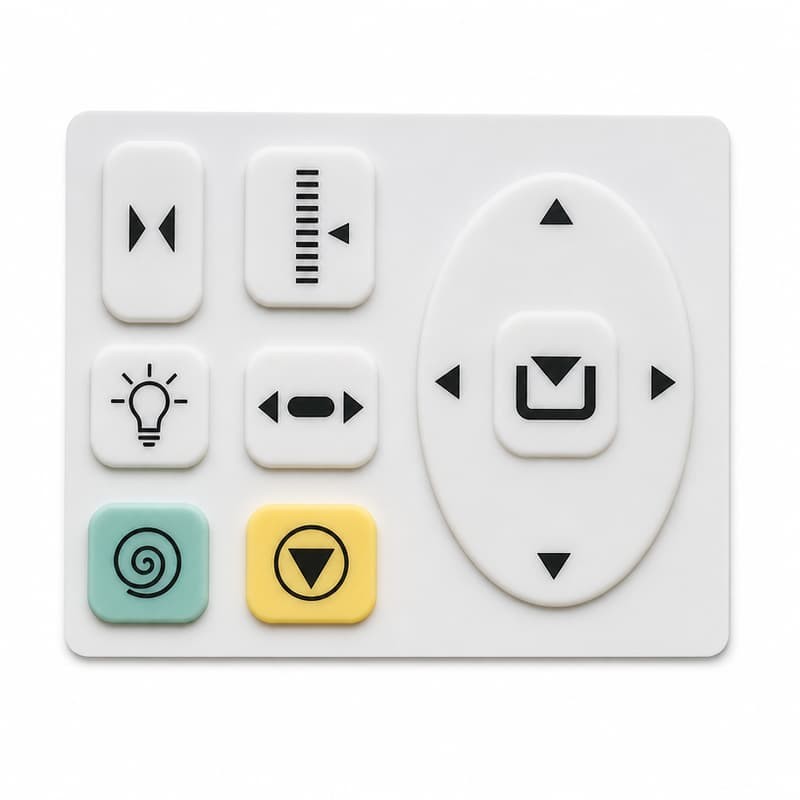
The parting line is where the mold halves meet, and on a keypad it is visible on every key flank. Its position decides whether flash appears on the pressing surface (bad - it changes tactile feel) or on the side (acceptable - it is trimmed). A well-designed mold places the parting line where flash is harmless, which is a geometry decision made in the tooling design phase. The flash control and deflashing guide covers the defect side; here the point is that flash starts at the parting line design, and no amount of deflashing fixes a bad line position.
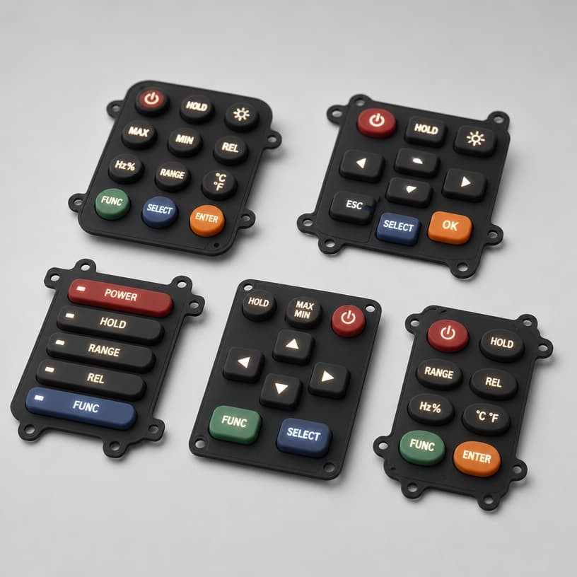
Cavity count is the production-volume lever: a 1-cavity mold is cheapest to build and slowest to run; 4–8 cavities multiply throughput and divide the amortized tooling cost per part. The trap is that more cavities multiply the risk of cavity-to-cavity variation - the four-cavity mold that produces three good keys and one 30 gF-soft key is a classic instrument-program complaint. Multi-cavity molds need a validation step that checks every cavity, not a sample from one. The cavity count balancing guide works through the cost arithmetic.
4. Tooling Validation: The Most Rushed Phase in Rubber Keypad Production
Tooling validation (trial molding, or the "first article") is where the mold proves itself - and it is routinely rushed because it sits between "tooling is done" and "production must start". The validation phase should verify: dimensional accuracy of every critical feature against the drawing; actuation force and travel; contact resistance; legend registration and adhesion; and finish consistency across cavities. Our analysis of the tooling validation phase shows why skipping a full validation week creates a year of production headaches.
Prototype molds have their own economics. A silicone prototype mold (often a soft tool) is much cheaper than production tooling and is the right place to validate geometry, feel and legend before committing to the production mold. The prototype mold cost guide explains when the prototype step pays for itself - usually the first time it catches a dimensional error that would have gone into production steel.
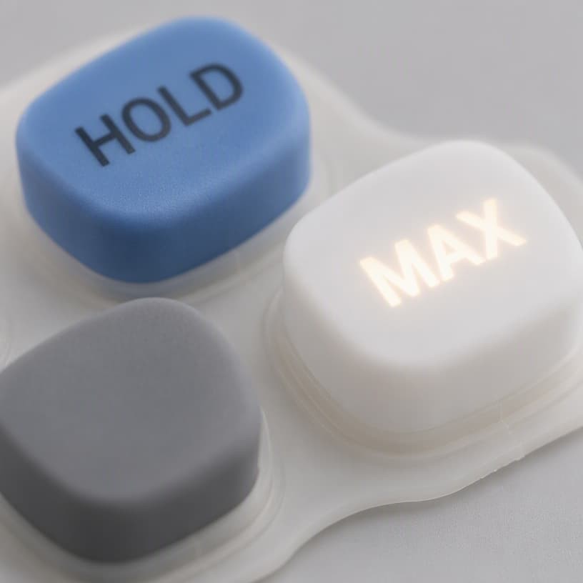
5. Case Study: A Tooling Choice That Tripled Handheld Meter Keypad Yield
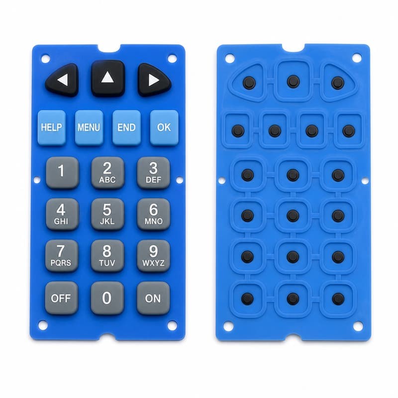
An instrument OEM's handheld meter keypad was running at 68% first-pass yield - flash on the pressing surface, dimensional drift, and legend misregistration. The supplier's answer was more deflashing labor. The real cause was in the tooling: the mold used a soft steel with a parting line that crossed the key pressing surfaces, and the four cavities had drifted out of match by 0.08 mm.
FromRubber rebuilt the tooling with three changes: hardened steel (S136), a parting line moved to the key side walls, and a cavity-matching validation step after 1,000 trial shots. First-pass yield rose to 94% and stayed there; deflashing hours dropped by two thirds; and the per-unit cost fell despite the higher mold price. The payback period was under three months of production - a number worth remembering when the cheap mold quotation arrives.
6. Rubber Keypad Tooling Checklist for Meter Production Programs
Choose steel grade against program volume and surface finish requirements
Place the parting line where flash is harmless - never on pressing surfaces
Balance cavity count against throughput and cavity-to-cavity variation risk
Validate every cavity, not one sample, before approving the mold
Use prototype tooling for geometry and feel validation before production steel
Confirm mirror/etch finish per cavity and lock the finish spec into the mold drawing
Sources and Further Reading
Tooling background draws on published material from Xometry - liquid silicone rubber molding design guide, Diamond HMI - rubber keypad manufacturing resources, and Google Patents - keypad mold designs. Yield and cost figures reflect FromRubber tooling records for instrument keypad programs.
Build the Right Mold the First Time
FromRubber designs and builds keypad tooling with hardened steel, validated cavities and parting lines engineered for zero pressing-surface flash. Request a tooling quotation with DFM review.
About FromRubber - FromRubber is a full-process silicone keypad manufacturer with in-house mold design, mold making, molding and validation, serving handheld instrument and electronics OEMs worldwide.