High Pressure Silicone Seals for Hydraulic and Pneumatic Systems
- Model
- BH-seals
Item specifics
- Design
- Follow 3D Drawing Or Physical Object
- Process
- Molding
- Feature
- Extreme Pressure Sealing
- MOQ
- 100000pcs
- Application
- Hydraulic and Pneumatic Systems
Review
Description
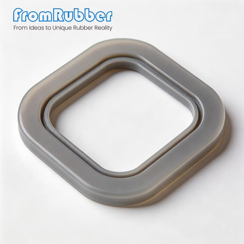
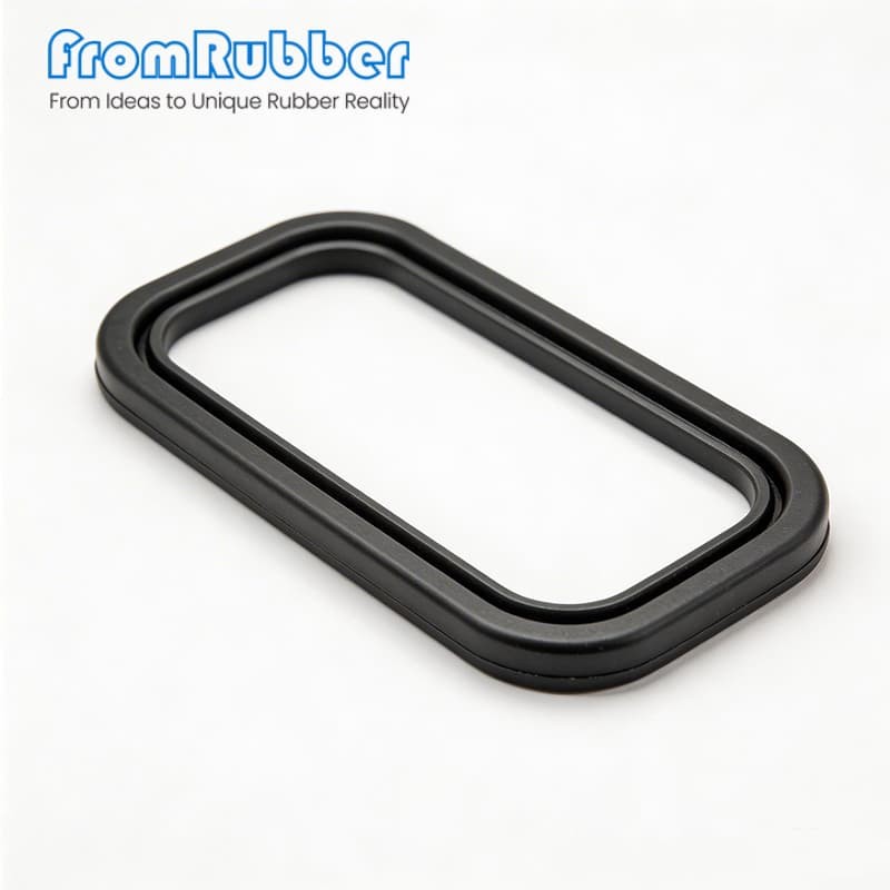
Hydraulic and pneumatic sealing A seal that weeps at 10,000 psi is usually not the wrong material, it is the wrong section for the groove it sits in. We mold HS70 silicone seals to your gland drawing: 15,000 psi dynamic capability with a backup ring, −60 °C to +230 °C, 70 ±5 Shore A, from 12 mm to 500 mm. Most of the seal failures we are asked to analyse are geometry failures, not compound failures: a groove too shallow for the pressure, a lip that cannot follow bore eccentricity, or a part that took a permanent set after its first heat cycle. Silicone helps with two of those — it keeps its elasticity at low temperature and it recovers after compression — and does nothing for the third if the gland volume is wrong. The HS70 compound we mold carries a tensile of at least 9.5 MPa, 320 % elongation and a compression set of 22 % or less after 22 h at 175 °C. That set figure is what decides whether the seal still pushes back after a thousand pressure cycles, and it is the number worth arguing about in a specification review. Pressure rating belongs to the section, not to the polymer. A U-cup with a backup ring and a step seal hold the same pressure very differently, and above roughly 10,000 psi the backup ring stops being optional. The table below is the starting point we use when a customer sends a gland drawing without a profile callout. Silicone earns its place against water-glycol, phosphate esters and synthetic oils, and in cold-start conditions where NBR has already gone brittle. It is the wrong answer in continuous hydrocarbon immersion, where volume swell is the limiting factor rather than heat. If your medium is engine oil or diesel, read our comparison of silicone and NBR for oil-pan service before you lock the drawing, then look at the fluorosilicone-modified gasket compound instead of a standard VMQ. Slow strokes and high side loads produce stick-slip long before the seal leaks. A bonded PTFE or molybdenum-disulphide surface on the dynamic lip removes most of it, at the cost of a harder part to inspect and a coating that has to be specified at drawing stage — it cannot be added to a finished mould. Tell us the stroke speed and the surface finish of the bore and we will say whether the coating is worth the extra step. We quote custom seals against drawings and annual volumes, not against cart quantities. This programme is for OEM, ODM and industrial replacement projects. Dongguan Bohao Electronic Technology Co., Ltd. IATF 16949:2016 / ISO 9001:2015 certified. Values shown are typical for the listed compound or platform; the drawing and the approved sample govern production.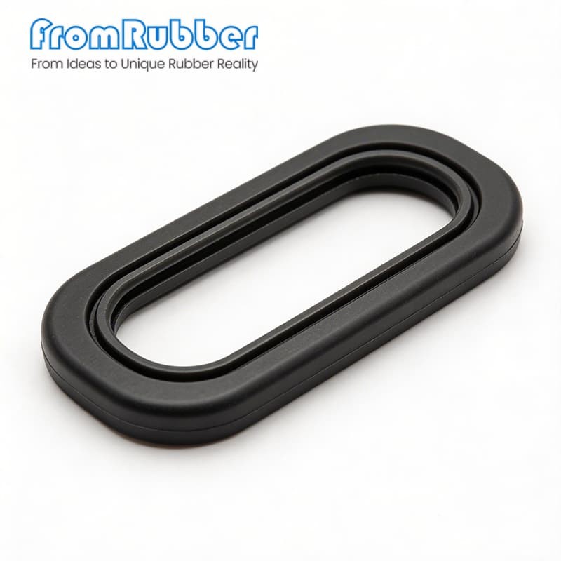
High pressure silicone seals, molded to your groove drawing
Where these seals actually fail
Choose the profile before the compound
Application Standard profile Size range Hydraulic piston seals U-cup / step seal 0.5–20 in (12–500 mm) Pneumatic rod wipers Double lip / scraper 0.25–12 in (6–300 mm) Rotary shaft seals Spring-energized up to 8 in (200 mm) Flange and static faces O-ring or custom molded any custom size Where silicone is the right answer, and where it is not
Low-friction options for slow, precise actuation
How a custom seal programme runs
What we need to quote
What comes back
Send a groove drawing for a sealing review
fromrubber.com
+86 18926836960