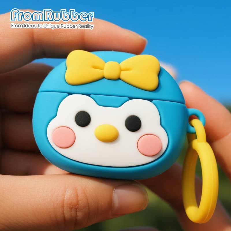
Silicone Earphone Case With hook and Lanyard– Lightweight Protection & Durable
Silicone Earphone Case With hook and Lanyard– Lightweight Protection & Durable
Model
BH-silicone case
Item specifics
Design
Follow 3D Drawing Or Physical Object
Process
Molding
Feature
Lightweight Protection,Durable & Shock-Absorbent
MOQ
1000pcs
Application
Earphone Charging Case
Review
Description
Moulded earphone case · integrated carry point
The hook is not a hole. It is a load path.
Most samples of this product fail in the same place: the eyelet. A character shell can look perfect in a 3D render and still tear at the carry point after eight weeks, because a hole in a flexible wall concentrates stress, and silicone has no yield point to absorb it.
We mould this earphone charging case as a two-part silicone shell with the eyelet, the hinge line and the port opening formed in the same tool. The artwork is what the buyer sees; the eyelet root, the split line and the shell grip are what keep the product in use.
One-shot moulded shell, top and bottom halves
Eyelet formed in the tool, not punched after cure
Colour built into the compound or set as separate moulded pieces
MOQ 1,000 pcs per design
Four load paths we design before we cut steel
Each one has a different failure mode. All four have to be resolved on the drawing, not in the moulding shop.
01
Eyelet root
The wall around the hole has to carry the pull of a case plus earbuds swinging from a bag. Thickening the whole shell is the wrong answer: it stiffens the part and changes how it grips the device.
Typical failure: crack starting at the inner edge of the hole, running into the side wall. Fix is a filleted boss around the eyelet, local wall build-up and a gate position that keeps the weld line away from the root.
02
Hinge split line
The lid line is the second wear point. It has to stay closed in a bag, open with one thumb, and not pinch the charging case seam when the shell flexes.
Typical failure: lid lifting, or the split line drifting across the artwork. Fix is split-line placement on a natural edge of the design plus a controlled land at the mating face.
03
Ring and hook interface
Silicone ring, split ring, webbing strap and snap hook all pull differently. The eyelet inner diameter has to match the hardware you specify, not the hardware we happen to stock.
Typical failure: metal ring sawing through a soft eyelet, or a strap that will not pass the hole at all. Fix is matching hardness and eyelet section to the hardware before sampling.
04
Shell retention
The shell must hold the charging case without stretching it out of shape. Grip comes from the return at the open edge, not from making the whole part undersized.
Typical failure: shell slips off in a pocket, or the lid pops open on impact. Fix is a moulded return lip with a relief channel so air escapes when the case goes in.
What you set before tooling
These are the variables that change the mould, so they are agreed in writing before a sample is cut.
Parameter
What you specify
Why it changes the tool
Device model
Charging case model, or a physical sample
Defines cavity, port position and lid arc
Shell build
Two-part shell with hinge line, one-piece sleeve
Two-part needs a split face and lid land
Carry point
Side eyelet, top eyelet, both, or none
Eyelet position drives gate and ejector layout
Hardware
Silicone ring, split ring, cord, snap hook, or supplied by you
Sets eyelet inner size and wall section
Hardness
Shore A 30–80, chosen against wall thickness
Soft grips better; firm holds the eyelet shape
Colour route
Tinted compound, separate moulded colour pieces, print, or a mix
Decides cavity count and assembly steps
Marking
Moulded-in logo, screen print, laser etch
Print and etch are post-cure operations
Tolerance
ISO 3302-1 M2 unless your drawing states otherwise
Sets inspection and sample approval
Not quoted as stock: every run is tooled to your artwork and your device. We do not sell ready-made character cases from a catalogue.
How the programme runs
Drawing or sampleSTEP, IGES, DXF or PDF, plus a physical sample if one exists.
DFM reviewEyelet root, split line, port clearance and colour route reviewed before quoting.
Sample toolSample tooling typically runs 3–5 working days, then a fit trial on your device.
ProductionProduction tool 10–12 working days, bulk typically 7–10 working days after sign-off.
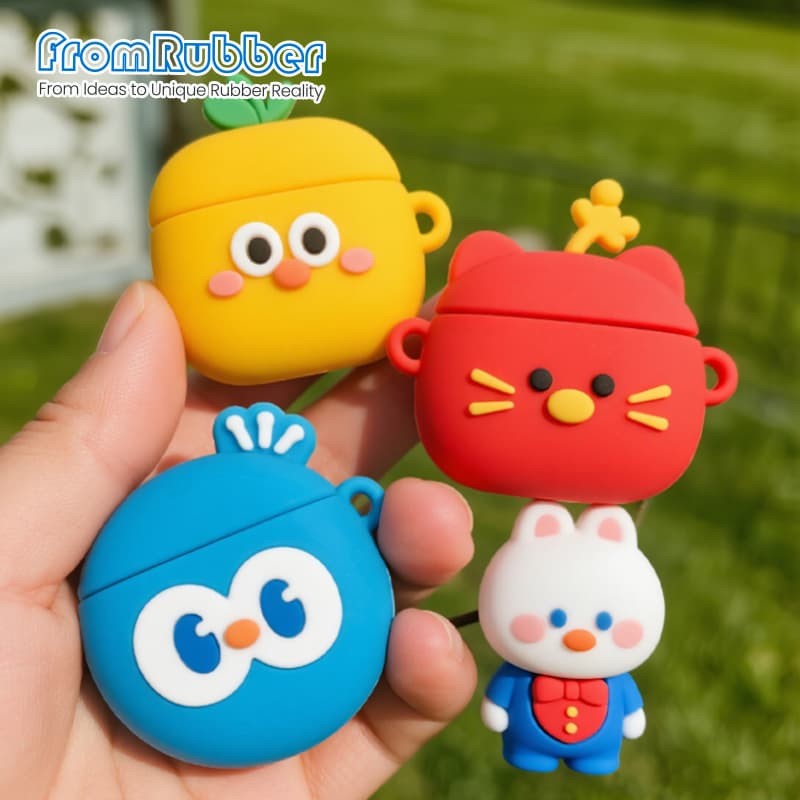
Carry points in production
Eyelet position, ring type and colour split are fixed per project. What follows is the same construction across three different programmes.
Questions we get from accessory buyers
Will the eyelet tear under normal carrying load?
It depends on three things: the wall section at the root, the fillet radius, and which hardware passes through it. We size all three against the load you expect, then test the first samples by hanging the loaded case from the ring. If the root is thin, we change the tool rather than the material.
Can the charging port and LED still be used with the shell on?
Yes, when the openings are drawn from the device model rather than copied from a similar case. Port cutouts are formed in the tool, so their position is fixed at sampling. Send the device model and we will mark the clearance you need for the plug body, not only the socket.
Do you supply the ring, or do we source it?
Both routes work. We can mould the silicone ring in the same colour as the shell, or leave the eyelet sized for hardware you supply. Mixed programmes are common: moulded ring for retail, metal split ring for promotional runs.
Is the character moulded, printed, or glued on?
Moulded or set as separate moulded colour pieces that sit in the tool and bond during cure. We do not glue decoration onto a finished shell for this product type, because the bond line is the first thing to fail in a bag.
Send the device model and the artwork
You get a DFM note on the eyelet, split line and port layout, plus a quote that separates tooling from piece price. If the shell needs a design change to survive daily carry, you hear it before tooling starts.