Small Rubber Grommets and Plugs for Detector | Custom Replaceable Silicone Seals
Item specifics
- Design
- Follow 3D Drawing Or Physical Object
- Printing
- Silk Screen Printing,Laser Etching
- Feature
- Dustproof,Sealing
- MOQ
- 1000pcs
- Application
- Leak Detector
Review
Description
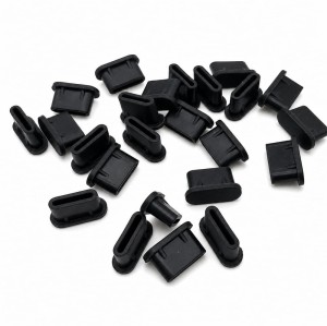
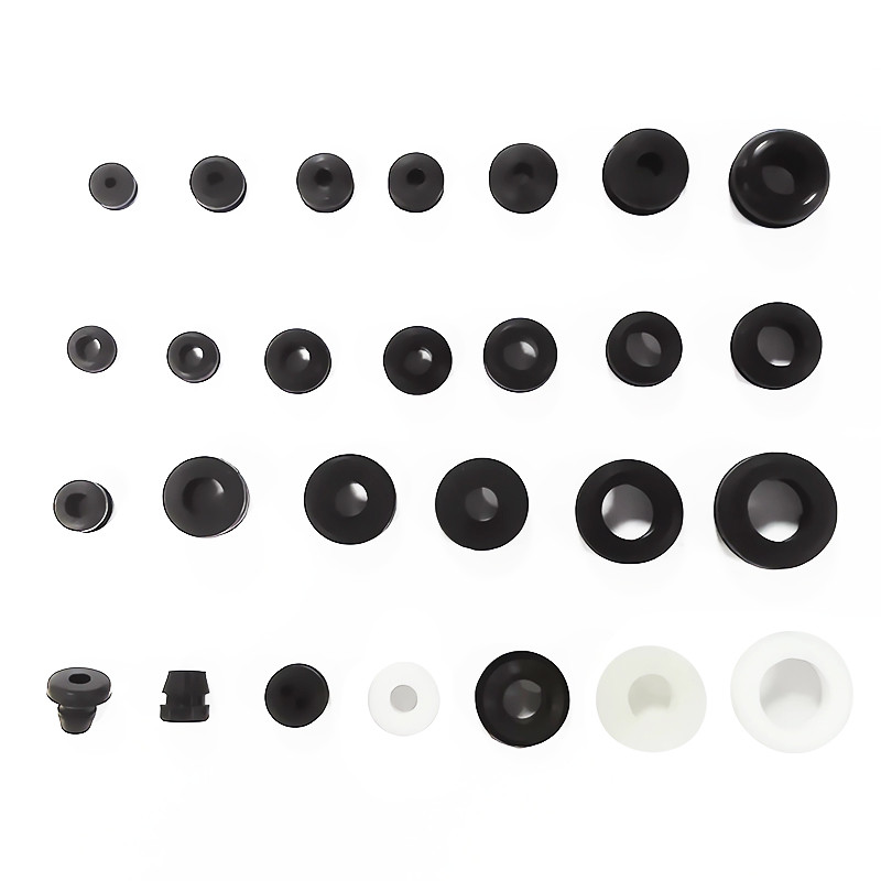
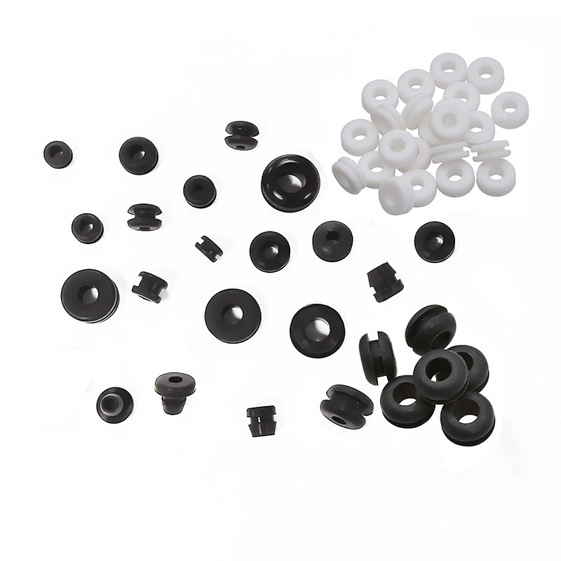
On a handheld detector, the smallest molded parts carry the longest tolerance chain. A cable grommet, a sensor port plug or an enclosure seal is usually the first item to be replaced after a field failure, and the way it was designed decides whether that replacement happens at a bench in ten minutes or becomes a warranty return. This page covers the three engineering decisions behind small silicone grommets and plugs: tolerance, replaceability and elastomer selection. A grommet sits between two parts that were each molded to their own tolerance: the housing bore and the cable or probe passing through it. The seal has to absorb the sum of those tolerances plus the movement of the cable in service. When the grommet is specified as a nominal size with no compression range, the assembly either leaks on the loose end of the bore tolerance or becomes impossible to fit on the tight end. Plugs fail differently. A port plug that is pressed in by hand depends on a retention feature, not on compression, and the feature is usually the first geometry to be simplified when a drawing is redrawn for cost. The result is a plug that seals on the first insertion and works loose after the port has been opened a few dozen times. Below roughly ten millimetres, the features that matter are the ones that are hardest to inspect: flash at the parting line, concentricity between the bore and the outside diameter, and the radius at the sealing bead. A flash line running across a sealing surface is a leak path that no compression ratio will close, so the parting line has to be placed away from the sealing land at the tooling stage rather than corrected by trimming afterwards. Concentricity is the second silent failure. If the bore and the outer diameter are moulded on the same core, the wall thickness stays uniform around the circumference and the grommet compresses evenly. When the geometry forces a split cavity, the wall varies and one side of the seal carries almost all of the compression. A bonded or overmolded grommet is cheaper to assemble and far more expensive to repair. Instruments that are serviced in the field benefit from a seal that a technician can remove with a pick and replace from a kit, with the same part number used in production and in service. That choice affects the housing: the bore needs a lead-in chamfer, a shoulder to seat against, and enough clearance for a removal tool. A service kit also changes the purchasing pattern. Instead of ordering seals only with housings, the customer orders a small number of part numbers in a defined kit, which keeps the seal drawing alive across production batches and makes the field-replacement part traceable to the same tool. Silicone is the default for detector seals because it holds its elasticity from low temperatures up to the range where most portable instruments operate, and it tolerates the alcohols used for cleaning. It is a poor choice against some oils and fuels, where NBR is the better answer, and it is not the most economical option for outdoor seals exposed mainly to water and ozone, where EPDM performs well at lower cost. The decision should be written into the drawing as a named material family plus the media the seal will contact, because the same geometry in two elastomers behaves differently in compression set. A seal that is correct in silicone and re-quoted in a cheaper rubber without re-checking compression set is a common source of field leaks. Values are fixed per project on the approved drawing and the material data sheet. Sizes below describe the scope of the part family rather than a stocked catalogue item. Yes. A sample can be measured and modelled, with the critical sealing dimensions confirmed against the mating bore before tooling. Where the bore is not available, the compression range is agreed on the drawing and verified on first article. The limit is set by wall thickness and the sealing feature rather than by overall size. Very small parts are reviewed on the drawing, because flash control and ejection usually decide feasibility before the dimensions do. Seal kits can be packed as a defined set of part numbers for field service, using the same tooling as the production parts so the service item and the production item stay identical. Silicone is the usual choice for instruments cleaned with alcohols and used across a wide temperature range. EPDM and NBR are considered when the seal contacts water and ozone only, or oils and fuels, and the recommendation is made against the actual media list. Seal performance depends on the bore as much as on the grommet. Send the housing section, the cable or probe diameter and the cleaning agents, and the review returns the compression range, material recommendation and the retention design for the number of service cycles expected.Small Rubber Grommets and Plugs for Detectors: Keeping a Sealed Instrument Serviceable
Why a Small Grommet Decides Whether a Detector Stays Sealed
The smallest part carries the longest tolerance chain

Tolerance Design for Sub-10 mm Grommets and Plugs
Flash, parting line and concentricity
Designing a Replaceable Seal Kit Instead of a Glued-In Grommet
Serviceability decided at the drawing stage

Material Choice: Silicone, EPDM or NBR for Detector Seals
Matching the elastomer to the medium, not to the price
Small Grommet and Plug Specification: Fields to Agree Before Tooling
Questions About Small Seals and Replaceable Grommets
Can you mold from a physical sample without CAD?
How small a part can be molded?
Do you supply seals as a kit?
Which elastomer should a detector seal use?
Send the Mating Bore With the Seal Drawing