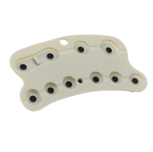
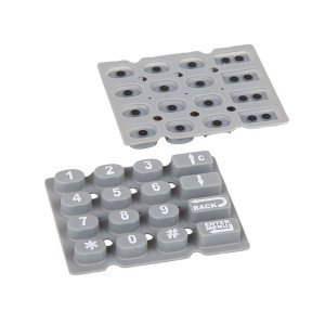
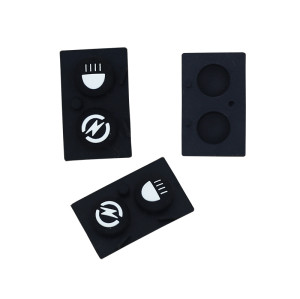
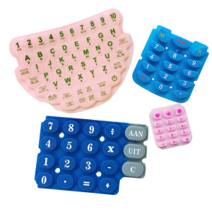
Conductive Silicone Keypad – Button Matrix, IP68 Rated, Carbon Pill Switches
Item specifics
- Design
- Follow 3D Drawing Or Physical Object
- Process
- Molding
- Feature
- Button Matrix,Conductive,IP68 Rated
- MOQ
- 2000pcs
- Application
- industrial, medical & automotive applications
Review
Description
Twenty-four keys wired individually need twenty-four inputs, a common line and twenty-four traces. The same keys as a six-by-four matrix need ten lines. That saving is the reason matrices exist, and the reason a keypad project so often starts with the wrong question: not "how many keys", but "how many lines can the controller spare, and can it scan fast enough". The answer changes the circuit, the pad layout, the ghosting risk and the sealing strategy. It should be settled before the keypad drawing is released, because a matrix that is decided late is a matrix that is wired badly. A matrix trades I/O pins for scan time and for a new failure mode. Pressing three keys that form a rectangle can produce a phantom fourth reading - ghosting - unless the design blocks it with a diode per key, or the firmware limits how many simultaneous keys it accepts. Three practical consequences: decide early whether multi-key presses are legitimate (rarely, on an instrument panel), check the scan rate against the controller's loop time, and keep the matrix wiring symmetrical so that trace resistance is similar across keys. Every pill is moulded, so every pill is slightly different: position, flatness, carbon loading. Across a large panel the spread between the best and worst key is what the firmware has to tolerate, not the average. That leads to three requirements that belong on the drawing: a maximum resistance per key rather than a typical value, a maximum force per key, and a defined pad geometry that is identical under every key. Pad design itself is covered under conductive control panels; here the point is that consistency across a large field matters more than the best single value. On a sealed keypad, each key is a place where the membrane flexes, and the perimeter is where water actually enters. Three hundred presses a day on thirty keys is nine thousand flex cycles a day on the same material, so the sealing question is not only static - it is fatigue. Most ingress comes in at the panel-to-housing bond or the tail exit, not through a key. Fix the perimeter first, then the keys. A key with a short, thick skirt resists water and feels stiff. A longer skirt feels better and moves more. The compromise is a dimension, not a preference. A sealed panel with many keys pushes air through the least-tight path on every press. A controlled vent path keeps the rating and stops the pumping. The key layout with legends, the matrix wiring (or the controller's available pins), the pad drawing, and the ingress requirement. With those four, the circuit and the mould can be priced in one pass. If the wiring is not yet decided, send the key count and the pin budget. A six-by-four and a five-by-five matrix look identical on a panel and behave differently in firmware, so the choice is worth an hour of design time. Press-cycle expectations are covered in how many press cycles a conductive keypad withstands, and the contact physics in the science behind conductive keypad buttons. Only if simultaneous presses must be decoded unambiguously. Most instrument panels accept one key at a time, so firmware blocking is enough and the diodes are saved. State the requirement explicitly. There is no fixed limit; the constraint is pad area and trace routing. Beyond a few dozen keys the matrix wiring and the circuit type become the deciding factors, not the moulding. Yes. Sealing requires a defined skirt and perimeter compression, both of which add force. Specify the force after assembly, and expect the sealed version to differ from the open sample. Yes, but they are different drawings: individual wiring changes the trace count, the tail and often the circuit type. Do not treat one as a BOM variant of the other. The matrix, the pad layout and the seal all follow from those two numbers plus the ingress requirement. Send them with the key layout, and we will return a wiring proposal and a moulding plan.A button matrix is an arithmetic decision before it is a moulding decision
Rows times columns, and the cost that comes with it
What the saving buys and costs
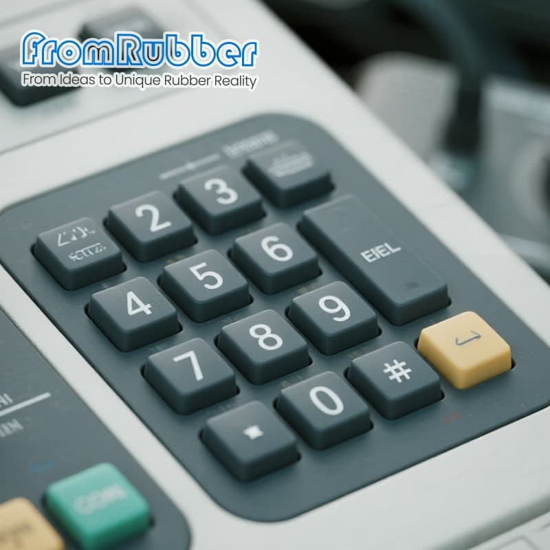
Carbon pills across thirty keys are not thirty identical switches
Spread is the specification

Sealing gets harder with every key you add
Perimeter before keys
Skirt geometry
Venting
What to send for a matrix quote
Four documents
Specification on this series
Questions from electronics and mechanical teams
Do I need a diode at every key?
How many keys can one panel carry?
Does IP68 change the feel?
Can the same panel be supplied with and without the matrix?
Send the key count and the pin budget