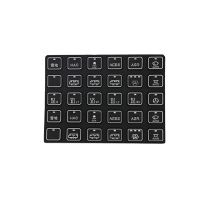
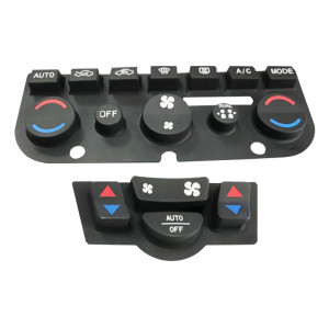
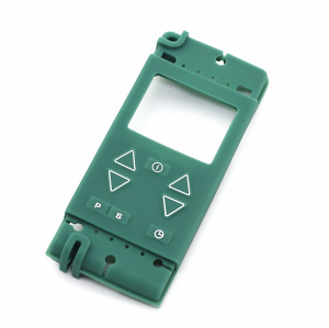
FPCA Silicone Membrane Switch Panel with Good Flexibility
Item specifics
- Design
- Follow 3D Drawing Or Physical Object
- Process
- Molding
- Feature
- Low-resistance
- MOQ
- 2000pcs
- Application
- industrial, medical & automotive applications
Review
Description
A flexible printed circuit assembly is a polyimide circuit with components and a connector already attached, laminated under the silicone overlay. On a switch panel it is the answer to a specific problem: the design has outgrown what printed silver ink can carry - too many traces in too little space, too much current for an LED string, or a connector that has to survive repeated plugging. If none of those apply, a printed silver-ink circuit is cheaper and thinner. Choosing FPCA for a simple three-key panel adds cost without adding function, which is why the right question is "what does my circuit actually have to carry", not "which is more advanced". A practical test: if the design has more than a few dozen traces, or any component other than the dome pads, price all three before committing. The crossover point is usually obvious once the layout is drawn. The tail is the only part of the assembly that moves. The overlay is bonded flat, the circuit is bonded flat, and the tail is asked to bend every time the product is assembled, serviced or dropped. Copper in a polyimide film tolerates a defined bend radius for a defined number of cycles - and very little else. Most "intermittent key" complaints we see trace back to the tail, not the keys: a cracked trace at the stiffener edge, or a connector that has been loaded sideways by a cable tie. The overlay and the circuit are different materials with different stiffness, and the adhesive between them has to hold them together across a temperature range without lifting at the edge. Three items belong on the drawing: A pressure-sensitive or heat-cured adhesive selected for the service temperature, not for ease of assembly. The wrong choice shows as edge lift after thermal cycling. The circuit has to sit flat within the bond area. A tail that lifts at the exit pulls the bond line with it, which is why the exit geometry and the bond are designed together. Decide whether a failed assembly is scrapped or reworked. A reworkable adhesive changes the process and the yield assumptions. Where the panel also has to be sealed to the housing, the perimeter bond becomes the sealing element and the requirement moves to the assembly: see IP67 membrane keypads. For how the whole stack is specified as one drawing, see membrane switch keypad assembly. Resistance budgeting on the circuit itself is set out under low-resistance FPC membrane switches. When the layout needs fine pitch or dense routing, when the panel carries components, or when a pluggable connector is required. On a plain matrix with a few keys, printed silver ink is usually the better commercial answer. Yes, with the FPCA route, and it is often the reason to choose it: a tested sub-assembly with a ZIF or board-to-board connector removes a hand-soldering step from your line. Yes. The circuit is thin and sits under the overlay, so the touch is set by the overlay and the dome, not by the carrier. A stiffener or a light-guide film is more likely to change the feel than the circuit is. It depends on the copper thickness, the film and the number of bend cycles. State the cycles and the installation space, and the radius and stiffener follow - a number quoted without those two inputs is not meaningful. Carrier choice, stiffener and connector all follow from trace count, current and how the tail has to leave the housing. Send the schematic or netlist with the mechanical envelope, and we will price the three carriers against the same layout.FPCA in a silicone panel: it is chosen for pitch and current, not for cost

Three carriers, three different limits
The tail is where panels fail in the field
Design rules that matter
Why it fails

Bonding a flexible circuit to silicone
Adhesive system
Flatness
Rework

Specification on this series
Questions from hardware and sourcing teams
When is FPCA worth the extra cost?
Can the connector be supplied on the tail?
Does an FPCA panel still feel like silicone?
What is the minimum bend radius for the tail?
Send the netlist and the tail constraint