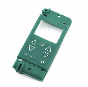
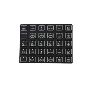
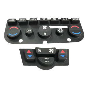
Backlit Silicone Membrane Switches with Metal Dome Assembly
- Model
- BH-membrane switch
Item specifics
- Design
- Follow 3D Drawing Or Physical Object
- Process
- Molding
- Feature
- Low-resistance
- MOQ
- 2000pcs
- Application
- industrial, medical & automotive applications
Review
Description
A backlit dome switch is five thin layers pressed together: overlay, adhesive, spacer, dome and circuit. The LED sits under one of them and the dome sits under another, and both have to work through the same stack height. That is the whole design problem - raise the overlay to make room for light and you change the travel the dome sees; thicken the spacer to stop light bleeding sideways and you change the force curve. Designing the two functions in one pass, with the stack defined first and the optics and touch tuned inside it, is what separates a panel that lights evenly and clicks cleanly from one that does neither. Light leaves a surface-mount LED at a wide angle, crosses a spacer cut-out, and exits through a translucent window in the overlay. Every air gap in that path loses light; every white surface in it recovers some. The window's distance from the LED matters more than its size. The dome snaps when the actuator - the moulded boss or the overlay itself - has pushed it through its travel. If the stack pre-loads the dome at rest, the click is lost before the customer ever presses it. The dome closes onto a pair of pads on the circuit. Contamination, oxide and pad finish change the resistance far more than the dome does, which is why the contact area is specified separately from the trace. Each layer is moulded, coated or laminated to its own tolerance, and they add. A design that works at nominal dimensions can fail at both ends of the stack: pre-loaded and never clicking on the thick side, dead and never contacting on the thin side. Sum the minimum and the maximum, and check that the dome still snaps and still releases at both ends. This is a two-minute calculation that prevents most "the click feels dead" complaints. Whichever route is chosen, the spacer has to be opaque outside the windows. Light bleed between keys is usually a spacer material decision, not an LED one. Measure the snap and the release force on the assembled panel, not on a bare dome. The curve is the only objective record of "good click". Photograph the panel in a dark room at the lowest and highest brightness the product offers. Hot spots that vanish at full brightness are still visible at night. Run to the number of presses the product claims, then re-measure contact resistance and force. The dome may survive while the adhesive around it does not. Cycle between the extremes in the specification. Differential expansion across five thin layers is what lifts a corner of the overlay. The lighting options and print layering for membrane switches are covered in backlighting, printing and layout options; diffusion problems on moulded keypads specifically are in backlight bleed and uneven glow; dome versus carbon pill actuation is compared in carbon pill versus metal dome. Yes, and it is the usual combination for instruments: a metal dome gives a crisp snap and a well-defined contact, while the illuminated overlay carries the legend. The two are separated by the spacer, which is why the spacer thickness is the critical dimension. Usually because it sits closer to the LED, or because the spacer cut-out around it is larger. Both are layout issues, not LED binning issues - check the distance from the emitter before changing the LED. Yes, and it should be designed at the same time. Removing the lighting layers changes the stack height and therefore the force curve, so a non-backlit variant is a stack revision, not a BOM deletion. More than the product's expected life, because the failure may be the adhesive rather than the dome. State the number and the acceptance criteria for force and resistance after the cycles. Window size, spacer cut-outs and actuator height are one decision, and they follow from the LED positions and the dome you choose. Send the overlay artwork with the PCB layout, and we will return a stack proposal with the tolerance chain worked through.Backlit membrane switch with metal domes: light and touch travel through the same stack
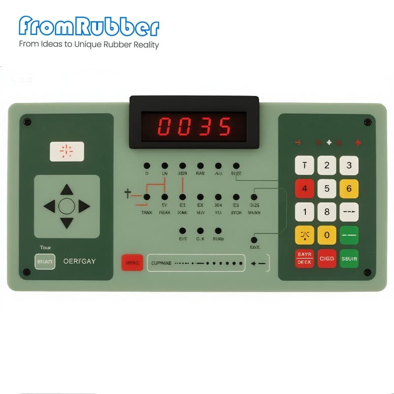
Three interfaces, one stack height
Light
From LED to window
Touch
From finger to dome
Contact
From dome to pad
The tolerance chain is where panels fail
The five dimensions to put on the drawing

Three ways to light a membrane panel
What to validate before release
Force-travel curve
Glow uniformity
Cycle life
Temperature
Specification on this series
Questions from panel designers
Can a backlit panel have a metal click?
Why does one key light brighter than its neighbours?
Can the same panel be offered in a non-backlit version?
How many presses should be specified?
Send the artwork and the LED layout together