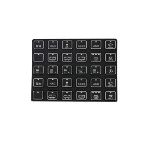
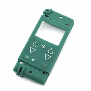
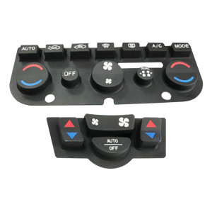
Electronic Membrane Switch Keypad Silicone Button Panel Switchs
Item specifics
- Design
- Follow 3D Drawing Or Physical Object
- Process
- Molding
- Feature
- Conductive,IP68 Rated
- MOQ
- 2000pcs
- Application
- industrial, medical & automotive applications
Review
Description
An electronic membrane keypad looks like a single item and is built from five: the graphic overlay, the adhesive, the spacer, the circuit and the tail. Each has its own tolerance, its own supplier and its own failure mode, and they meet at the press. That is why most keypad problems are drawing problems - never specified, so never inspected. The useful deliverable from a design team is therefore not just artwork. It is a drawing that defines each layer, the registration between them, the tail geometry and the mounting, in terms a mould shop and a laminating line can both work to. Four of the five are thin films, and all four are laminated in one operation. That is why a change to any single layer - a thicker hard coat, a different adhesive, a new spacer - is a stack change, not a component change, and has to be re-qualified. A drawing without a datum is the single most common reason a second batch does not match the first. The mould is the same; the assumption about which edge is the reference is not. Overlay legends have to sit over the correct pads. Between the artwork and the pad there are at least three tolerance sources: the artwork's own dimensional accuracy, the print or mould shrinkage, and the lamination placement. They add, and the sum is what the user sees as an off-centre icon. Supply artwork at final size, with registration marks. Scaled artwork introduces a percentage error that grows across the panel - small in the centre, visible at the edges. Moulded silicone and printed film do not shrink identically. The allowance is applied by the supplier, but it has to be stated, because it changes the pad positions on the circuit. Measure the offset of the worst key on the first article, in both axes, and record it. If it is half the tolerance budget, the process is already at risk. Sealing adds a requirement to the same drawing: the perimeter bond becomes a gasket, and the panel is only as watertight as the surface it is bonded to. Three items follow. Width and continuity of the adhesive perimeter, and the surface finish of the housing it seals against. A bond onto a textured or contaminated surface leaks regardless of the adhesive. A sealed panel traps air. Temperature cycling pushes it through the weakest point; a vent or a controlled leak path is a design decision, not an omission. A stiffer overlay or a heavier bond line raises the force needed to press. Specify the force after sealing, not before, or the panel will feel different from the sample. Sealing design for keypads is covered in IP67 membrane keypads, and the moulded-keypad version with IP68 contact in IP68 rated conductive keypads. If the choice between a membrane panel and a moulded keypad is still open, see keypad versus membrane switch. A vector file is a starting point, not a drawing. We need the layer stack, the pad positions, the dome specification and the tail geometry before a quotation means anything - otherwise the first article becomes the specification. It is shared: the artwork sets the legend positions, the circuit sets the pads, and the lamination sets the offset. Put a single number on the drawing for legend-to-pad offset and one party is accountable for the result. Rarely, once laminated. That is why the sub-assemblies are tested before the final press where the volume justifies it, and why the tail connector is often the only serviceable joint. Layer count, colour count on the overlay, circuit type, dome count and the test regime. A panel with ten domes and a ZIF connector is a different product from a three-key printed circuit, even at the same size. We will build from artwork, but the quotation and the first article both depend on the layer stack, the datum and the tail. Send the artwork with the PCB layout and the housing envelope, and we will return a stack proposal and a drawing checklist.A membrane switch keypad is five parts specified as one assembly
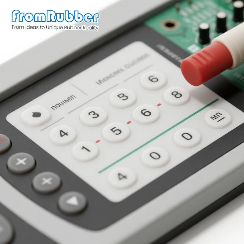
The five layers and what each one decides
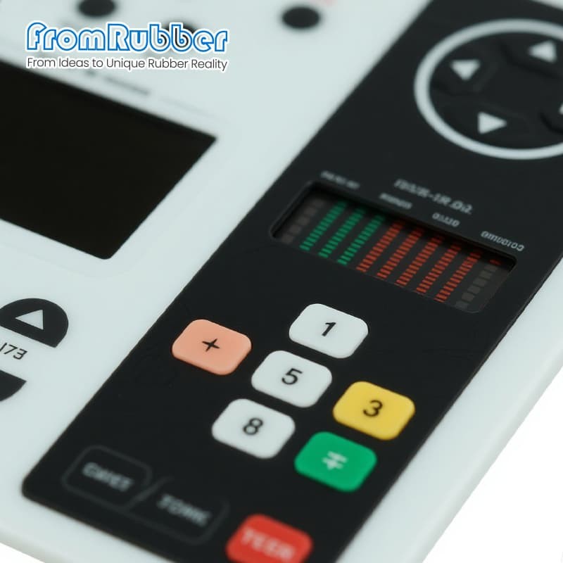
What a buildable drawing contains
Seven items that are always asked for
And three that are usually missing
Registration is the error that ruins a batch
Artwork at 1:1
Shrinkage allowance
First-article check
When the panel has to be sealed
Bond line
Pressure equalisation
Actuation force
Specification on this series
Questions from design and sourcing teams
Can we start from a PDF of the artwork?
Who owns the registration tolerance?
Can a keypad be reworked if one key fails?
What drives the unit price?
Send the stack, not just the picture