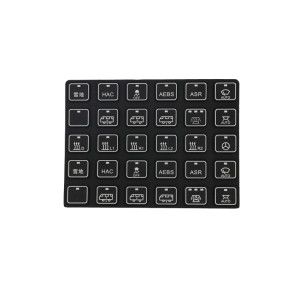
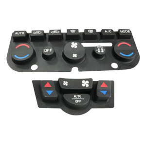
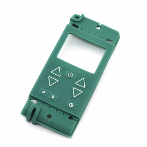
Custom Low-resistance FPC Silicone Membrane Switch
Item specifics
- Design
- Follow 3D Drawing Or Physical Object
- Process
- Molding
- Feature
- Low-resistance
- MOQ
- 2000pcs
- Application
- industrial, medical & automotive applications
Review
Description
Two suppliers can both quote a low-resistance FPC membrane switch and mean completely different things: one measured the trace with a two-wire meter, the other measured the closed contact with a four-wire method at rated current after a hundred thousand presses. The numbers look comparable and are not. On a switch panel, resistance is a budget spread across four places - trace, contact interface, connector and plating - and each one behaves differently with current, temperature and wear. Writing the budget down is what turns "low resistance" into something a factory can build and a buyer can inspect. Resistance rises with trace length and falls with width and copper thickness. On a printed silver circuit, the ink's sheet resistance dominates; on an FPC, copper thickness and trace width do. The dome or carbon pill touching the pads is usually the largest single term, and the one that changes most over life. Pad finish, contamination and contact force all move it. A ZIF or board-to-board connector adds its own contact resistance, and it is the term most often left out of a budget because it lives on the tail rather than the panel. Plated pads, carbon-coated contacts and printed silver all age differently. A plated pad can oxidise in storage; a carbon coating trades resistance for wear resistance. Ohm's law does the work: a 20 mA signal through 2 ohm of total path loses 40 mV. On a 3.3 V logic input that is usually harmless. On a 1.8 V rail it is 2 percent, and on an analogue sense line it is an error term that has to be calibrated out. The point is not the specific number - it is that the acceptable resistance follows from the circuit, not from the catalogue. In a scanned matrix the resistance sits in series with the scan line, and the controller resolves the difference between a pressed and an unpressed key by voltage. As contact resistance rises with wear, the margin between "pressed" and "noise" narrows. That is why the end-of-life figure, not the initial figure, is the one to specify. State it after the cycle count the product claims. A requirement written this way can be inspected at goods-in with a bench meter and a fixture. A requirement written as "low resistance" cannot be inspected at all, which is why it usually ends in a dispute about method rather than about product. A two-wire meter includes the lead and probe resistance in the reading. On a contact in the milliohm range, the leads can be most of the number. Use four-wire, or zero the leads and say so on the report. Contact resistance on a fresh dome is at its best. The figure that predicts field behaviour is taken after cycling, and often after a temperature soak, because that is when the contact interface has settled. Choosing between printed ink, FPC and a full FPCA is covered in FPCA silicone membrane switch panels. For the overall panel stack and what belongs on the drawing, see membrane switch keypad assembly. It depends on what the circuit has to do. A key matrix in a battery device tolerates far more than an analogue sense line or an LED string. Set the limit from the circuit's error budget, then let the supplier choose the construction that meets it. Usually on initial contact resistance, yes, but not always after wear. The dome wins on consistency; a carbon pill can win on durability in a dirty environment. Specify the end-of-life figure and test both if the margin is tight. Yes, at the contact interface and at the connector. If the product operates over a wide range, take the reading at both ends rather than at room temperature only. A fixture that presses every key at a defined force, with a four-wire meter on the tail. Record per-key values, not an average - a lot mean can hide one bad key that will be the field failure. Tell us what the signal has to survive - current, supply voltage, tolerable drop - and we will propose a construction and a measurable limit. The drawing then carries the method, the current and the cycle count, so goods-in inspection means something."Low resistance" is not a specification until it states a method, a current and a cycle count
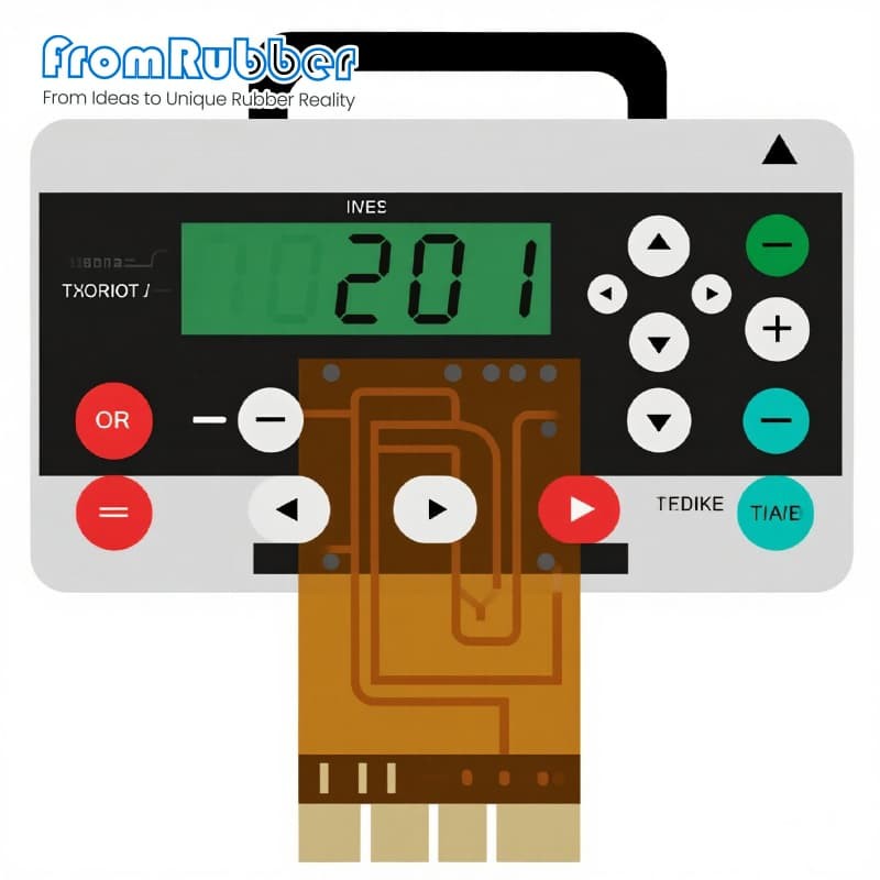
Where the ohms actually come from
Trace
Length × resistivity
Contact
The closing interface
Connector
Two more interfaces
Plating and ink
The quiet variable
Why the number matters: two calculations
Voltage drop on a signal line
Scanning a matrix
How to write the requirement
Two measurement mistakes that cause most arguments
Measuring with the wrong leads
Measuring a single press
Specification on this series
Questions from electrical and quality engineers
What counts as low resistance for a membrane switch?
Does a metal dome always beat a carbon pill on resistance?
Can resistance drift over temperature?
How do I check incoming lots?
Send the circuit's error budget, not a target number