Silver Aluminum Conductive Silicone Rubber Strip Good Shielding Performance
- Model
- BH-Conductive Silicone Rubber Strip
Item specifics
- Processing Service
- Moulding, Cutting
- Place of Origin
- Guangdong, China
- Application
- Microwave Waveguide System,Metal boxes sealing
- Volume resistivity
- 0.004 Ωm
- Style
- Ag/Al conductive rubber
- Feature
- conductive and sealing
- Filler
- Ni/C,AL/Ag,AL/Cu,AL/Glass
- Shielding effectiveness
- >90db
- Temperature Ranges
- -60 to +185 ºC
Review
Description
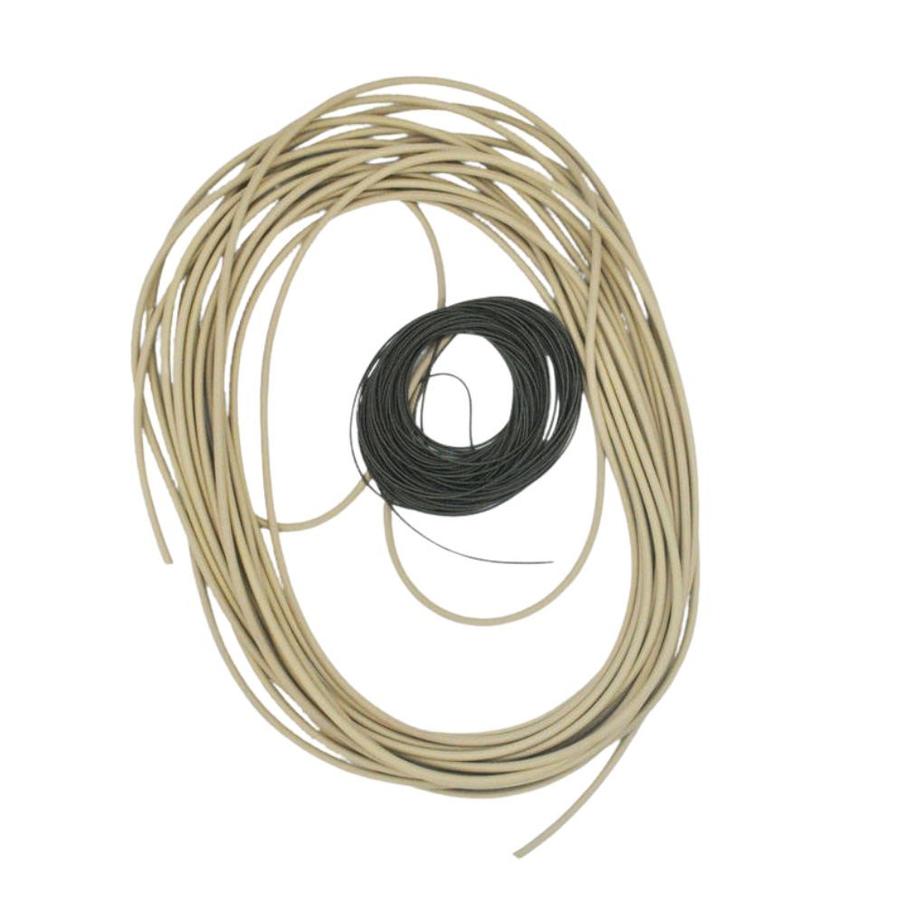
This strip is a compression gasket, not a conductor in the wiring sense. It seals a joint against dust and moisture and, at the same time, carries RF current across that joint. It is the right part when a die-cast aluminium housing, a waveguide flange or a shielded cabinet door needs sealing and grounding from one component, and when you cannot rely on a welded or screwed bond at the mating face. It is the wrong part in three situations, and each of them explains a large share of the field returns we examine: a groove that is machined too deep, so the strip never reaches its working deflection; a door that flexes, where a braided strap or a finger-stock contact belongs; and a contact face that is painted, anodised or chromate-coated, which insulates the very surface the strip is meant to bridge. The material is an Ag/Al filled silicone elastomer: a beige base compound loaded with silver-coated aluminium particles, so conductivity runs through the whole cross-section rather than sitting in a coating that can rub off. Conductive silicone is not one material. The filler decides conductivity, corrosion behaviour and price, and the four systems offered on this series are not interchangeable. Read the table as a shortlisting tool, then confirm the choice against your own corrosion and attenuation test. One page cannot rank these for you. The correct answer depends on frequency band, mating surface, closure force, salt spray and target cost, which is why a drawing plus a test band is more useful to us than a product name. Volume resistivity in ohm-metre and ohm-centimetre differs by a factor of one hundred. A quotation that states a number without a unit is not comparable with another supplier's, and a decimal point moved one place can make a 0.4 ohm-cm part look like a 0.004 ohm-cm part. Fix the unit in the RFQ. Volume resistivity depends on electrode area, probe pressure and conditioning. Shielding effectiveness depends on the test fixture and the frequency band. Ask for the method, not just the result, and keep the same method for incoming inspection. Every attenuation figure assumes a deflection. Conductive elastomer joints are normally designed in the 10 to 30 percent deflection range, then verified by compression-set testing at the real groove depth. A strip tested at 30 percent will not repeat its number at 10 percent. Almost none of the failures we see are material failures. They are geometry and assembly failures, and they are cheap to design out. A groove that is 0.2 mm too deep can drop the joint below its working deflection across the whole perimeter. Specify the groove as a band, for example a target deflection with a minimum, and measure the first-off assembly rather than the loose part. Mitred cuts at a rectangular corner leave a wedge-shaped gap. Either specify a moulded corner, a vulcanised splice, or an overlap long enough to survive the compression cycle. Anodised, painted or powder-coated flanges insulate the gasket from the housing. Mask the contact band before coating, or specify a conductive finish on that band only. Heat and time relax the elastomer. For doors that stay closed for years, ask for compression-set data at your service temperature, not at room temperature. Bring the strip and the mating plate to the same temperature and humidity used in the specification. Resistivity measured on a cold part is not the number on the drawing. Use one fixed electrode geometry and one fixed pressure, and record both on the report. Compare only against results produced the same way. Shielding effectiveness is a curve. Check the frequency range that matters for your product, not a single headline number. Clamp the strip into the real groove, at the real torque, and measure the closed joint. This is the only figure that predicts field behaviour. Repeat the assembly measurement after heat ageing and after a compression-set cycle. A joint that passes cold and fails warm is a design problem, not a batch problem. Production samples typically follow about two weeks after drawing release, subject to profile and tooling. Background reading on the material family, including how filler loading changes attenuation, is in how conductive silicone works in EMI shielding. For sealing profiles that carry no conductive filler, see custom silicone seals. No. It is a material-level figure measured in a fixture. Your enclosure result depends on groove depth, fastener pitch, surface finish, cable penetrations and seam length. Treat the material figure as a screening value and test the assembly. Only if your attenuation margin is comfortable and your corrosion environment is mild. Ag/Cu carries more conductivity; Ag/Al carries better cost and, in many cast-aluminium joints, more predictable galvanic behaviour. Requalify either way. Yes. Die-cut, kiss-cut and slit-to-width formats are all supported, which suits high-volume assembly where a loose strip would be slow to place. Send the frame outline with the drawing. Adhesive backing helps placement but is not a substitute for compression. Design the groove to hold the strip mechanically, then use backing only to keep it in position during assembly. We mould Ag/Al and the other three filler systems on the same platform, so the useful conversation is about your joint: deflection, mating metal, frequency band and quantity. Send a cross-section and we will return a profile proposal and a sample strip for your own test.Silver-plated aluminium silicone strip: a gasket that must do two jobs at once

Four filler systems, four different purchasing decisions
How to read the numbers on this page
Unit discipline
Method discipline
Compression discipline
Where these strips fail in the field
Groove depth
No deflection, no conductivity
Corner radius
Cut corners open the joint
Surface finish
Coating blocks the path
Compression set
The seal relaxes, the shield degrades
Incoming inspection in five steps
Condition the sample
Measure resistivity by method
Sweep the band you care about
Test the assembly
Age it
What to send with an enquiry
A useful RFQ package
What we return
Questions buyers ask before the first sample
Does "above 90 dB" apply to my enclosure?
Can Ag/Al replace Ag/Cu without requalification?
Can the strip be supplied die-cut to a frame?
Is a conductive adhesive backing available?
Send the groove drawing, not a product name