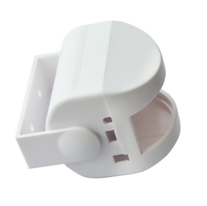
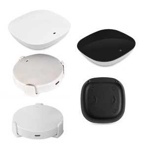
DIN Rail Mount Plastic Enclosure - Compact Modular Electrical Case
- Model
- BH-Plastic Enclosure
Item specifics
- Design
- Follow 3D Drawing Or Physical Object
- Process
- Injection Molding
- Feature
- Secure & Rustproof
- MOQ
- 1000pcs
- Application
- Outdoor
Review
Description
Panel build components Panels get filled with dead space because the enclosure was picked from whatever size the supplier had, not from what the module needs. This platform comes in six internal sizes from 120 × 90 × 55 mm to 360 × 240 × 105 mm, so a relay and a PLC card do not have to share one box. Size selection is a volume question and a height question at the same time. The table below is the one we use on the phone, because it answers both without a CAD session. The case clips onto TS35/7.5 and TS35/15 rail to IEC/EN 60715 with integrated snap-on clips — no bracket, no screwdriver in the panel. The part of the design that matters after installation is clearance: we recommend 10 mm between adjacent enclosures so heat can leave the side walls and cable can be dressed without kinking. The argument for rail-mounted housings — panel density, standard footprints, service access — is covered in our note on streamlining industrial control panel builds. This page is about the part itself: which size, which knock-out pattern, which cover, and what changes when the module inside changes. Pre-moulded entries are supplied for PG7, PG9, PG11, PG16 and M20 glands, on the bottom face or the sides. Getting this right at drawing stage is worth more than it looks: a knock-out added later is a drilling operation, and a drilled entry is the first place an IP66 enclosure starts to leak. Where the panel uses a mix of gland sizes, we cut a mixed pattern rather than leave unused holes open. The cover closes onto a silicone gasket with four screws at 0.6–0.8 Nm. That torque range is not a suggestion: under-torque and the gasket never reaches its design compression, over-torque and the boss around the screw cracks on the third service visit. A transparent cover lets a maintenance technician read status LEDs without opening the enclosure, which is usually why panels specify it; a hinged cover is available where access is frequent. Custom knock-out patterns, pre-drilled mounting holes, EMI/RFI shielding coating, UV-stabilised compound, colour matching to RAL or Pantone, moulded brackets and laser marking are all handled as tool inserts rather than new tools wherever the geometry allows. Standard colours are light grey RAL 7035 and black RAL 9005; anything else is a bulk run. Tell us what goes inside and which glands the panel uses. The reply is a size recommendation with the knock-out pattern drawn on it — not a catalogue page. Dongguan Bohao Electronic Technology Co., Ltd. IATF 16949:2016 / ISO 9001:2015 certified. Values shown are typical for the listed compound or platform; the drawing and the approved sample govern production.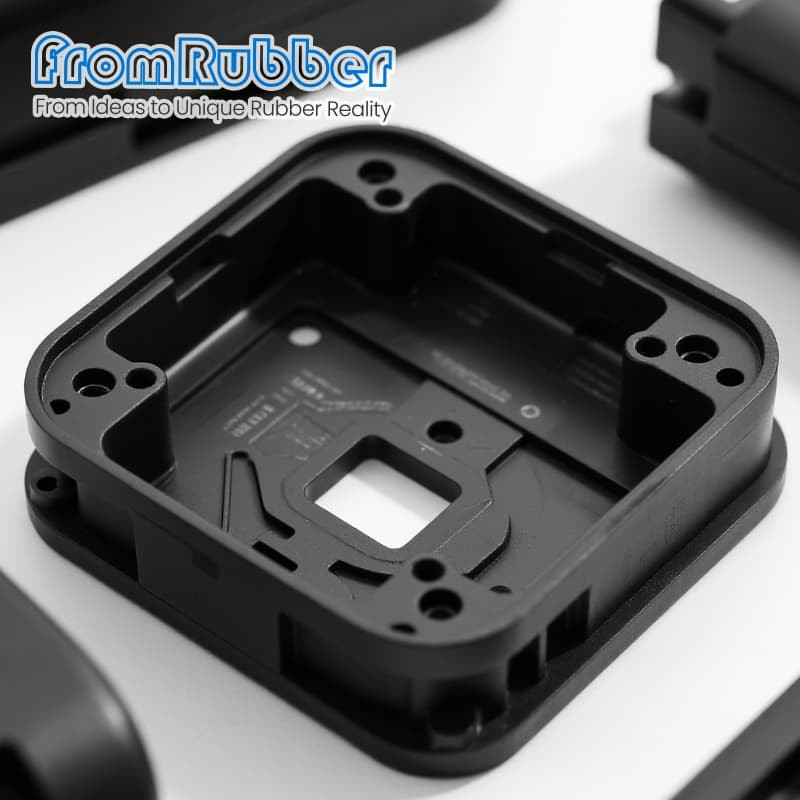
A DIN rail enclosure sized for the module, not for the rail
The six sizes, and what each one is for
Model Internal size (mm) Volume Max component height Typical contents DIN-PE120 120 × 90 × 55 0.59 L 80 mm Single relay, sensor interface DIN-PE160 160 × 110 × 65 1.14 L 100 mm PLC module, small controller DIN-PE200 200 × 140 × 75 2.10 L 120 mm Power supply, circuit breaker DIN-PE240 240 × 170 × 85 3.46 L 150 mm Multi-circuit control, I/O DIN-PE300 300 × 200 × 95 5.70 L 180 mm Comms equipment, meters DIN-PE360 360 × 240 × 105 9.07 L 220 mm Large controllers, modular systems What the rail interface has to do
Why DIN rail at all is already written
Knock-outs decide the cable plan
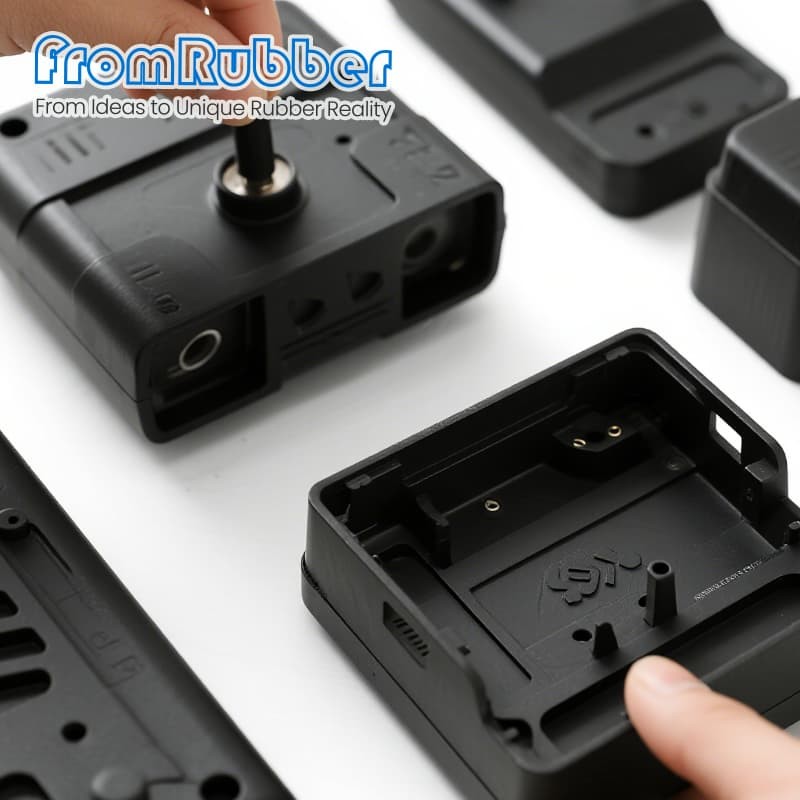
Sealing the cover
What we change for an OEM programme
What we need to quote
What comes back
Send the module list, get the size back
fromrubber.com
+86 18926836960