18v21v Output Adapter DIY Wire Connector
- Model
- BH-output Adapter
Item specifics
- Material
- ABS+Metal
- Color
- Black
- Application
- Output Adapter
- Features
- Portable
- MOQ
- 300pcs
- Package
- Opp Bag
- Weight
- 70g
- Line Length
- 8cm
Review
Description
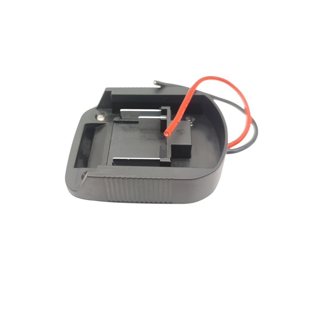
This adapter takes power out of a tool battery through two leads and presents it at the same voltage to another device. It does not charge, and it does not convert voltage: the output equals the pack voltage, less the drop across the leads and contacts. That single sentence decides whether the part is right for your programme - it is a discharge tap for OEM accessory design, not a power supply. It is built as an ABS housing with metal contacts and an 8 cm lead, weighing around 70 g. For a brand building a light, a pump, a fan or a test jig around an existing battery platform, that is usually the shortest route to a working accessory without developing a new pack interface. For anything that needs regulated output, it is the wrong starting point. Two limits belong in your instruction manual, not only in this page: the adapter must be removed when not in use, and it must never be connected to a charger. Both are stated on the existing product documentation and both prevent the most common misuse claim. An adapter this simple still has four interfaces, and each one has a measurable acceptance criterion. Put the numbers in the drawing and the part becomes repeatable; leave them out and every batch becomes a discussion. Specify a pull-out force on each terminal and a cycle count for insertion and removal. Contact retention, not moulding quality, is the usual cause of intermittent output in the field. If the interface geometry allows a reversed fit, the electronics downstream will see reversed polarity. Either the housing must mechanically prevent it, or the lead set must be marked and keyed at the connector. The lead exits a rigid ABS body, so the bend radius at the exit is the fatigue point. Specify a strain-relief boot or a moulded transition, then test by flexing at the exit rather than at mid-lead. Continuous current heats the contact interface. Give us the current and duty cycle, and wire gauge becomes a calculated item rather than a guess. Under-specified wire shows up as a warm lead and a voltage sag, not as a clean failure. The housing needs to be stiff enough to hold the interface geometry, accurate enough to key into the battery foot, and cheap enough to mould in volume. ABS does that. The conductive path needs low resistance and spring retention, which an elastomer cannot deliver, so the contacts are metal and the housing insulates everything else. That split is also the reason the part can be customised quickly: changing the lead, the terminal or the colour does not require a new structural concept, only a revision to the drawing. Where the programme needs a sealed or overmoulded version - a rubberised grip, a potted lead exit, or a silicone boot over the joint - the housing can be developed as an insert-moulded assembly. The same engineering logic is covered in insert moulding metal contacts into plastic parts, and housing-only projects sit under custom plastic enclosures. Battery platform and foot geometry, or a sample pack. A photo of the foot with a scale is enough to start; a 3D scan or drawing shortens the loop. Nominal voltage, continuous current, duty cycle, and the connector you want at the free end. These four numbers size the wire and the contact. Annual quantity, first-order quantity, packing format, and whether the part carries your brand marking. MOQ for the standard build is 300 pieces. For a new mould, DFM feedback is returned within 48 hours of a complete drawing, and a first sample typically follows about two weeks after drawing release. If you already have a working sample, send it: reverse-engineering an existing adapter is often faster than describing one. No. It is a discharge path only. Connecting it to a charger is outside its design intent and is explicitly excluded in the product documentation. No. Output equals pack voltage minus lead and contact losses. If you need a regulated or reduced output, the conversion belongs in your device, or in a separate DC-DC module inside the housing. It is used across both nominal classes, but fit is a function of the battery foot geometry, not the voltage label. Confirm the platform before tooling, because two brands can share a voltage class and share nothing else. Yes. Lead length, terminal type, housing colour and marking are drawing-controlled. Changes to lead length or gauge should be re-checked against the current rating, since both affect voltage drop. Send the battery platform, the load and the quantity. We will come back with a housing and lead proposal, the contact and wire sizing behind it, and a sample for your own electrical and drop test.18V / 21V output adapter: an interface part, not a charger
The specification that matters for a release drawing
Four things to audit before you release tooling
Terminal retention
Does the contact stay seated under load?
Keying and polarity
Can it be fitted the wrong way round?
Strain relief
Where does the lead fail first?
Contact heating
What current at 21V, continuously?
Why ABS with metal contacts, and not one material
The reasoning

What to send for a quotation
Interface
Electrical
Commercial

Four questions that decide the specification
Can this adapter charge a battery?
Does it convert 21V to 18V, or 18V to 12V?
Will it fit both 18V and 21V packs?
Can the lead length and terminal be changed?
Build the accessory around the pack you already sell