Injection Plastic Shell for Dashboard | Electric Vehicle Plastic Enclosure
Item specifics
- Design
- 3D Drawings or Objects
- Surface
- Polishing
- Service
- Free Consult
- MOQ
- 1000pcs
- Application
- Electric Vehicle Dashboard
Review
Description
An electric vehicle dashboard shell is judged on two things the drawing cannot fully describe: whether it stays flat after moulding, and whether the visible surface reads as one continuous plane under raking light. Both come from wall thickness discipline, rib proportion and gate placement - not from the resin data sheet. A shell that measures inside tolerance but shows a sink mark or a shadow line will be rejected at the customer's appearance audit. The part also has to survive the cabin: heat soak, sunlight, cleaning agents, and clips that are pushed in and out during service. Getting the appearance right and the structure wrong produces a part that looks correct and rattles within a year. Warpage is a shrinkage imbalance, so the fix is geometric before it is process-based. Once the tool is cut, the remaining levers are pack pressure and cooling, which are far less powerful than wall design. Every thickness step is a shrinkage step. A shell designed with a nominal wall and gradual transitions warps less than one with a thick boss land next to a thin panel. Where a step is unavoidable, a taper over several millimetres is better than an abrupt change - the eye reads the resulting flow mark as a defect even when the dimension is correct. Ribs stiffen the shell but pull the surface down. A rib thickness of roughly 0.5-0.6 of the wall keeps sink below the visible threshold on most filled grades, and ribs should be shorter than about three times their thickness to avoid a heavy mass at the root. Deep cavities and sharp rib roots are the two most common reasons a good design still shows a shadow. Gate position decides where the weld line lands, and on a class-A part the weld line must not land where it can be seen. A flow analysis before steel is cut costs far less than a tool rework. Texture also helps: a fine matte texture hides flow marks that a high-gloss surface would expose. The envelope below is a starting point for an interior dashboard shell. Material grade and tolerance class follow the vehicle programme's own standard. Values describe a typical design envelope and are not a substitute for the programme drawing. Dimensional and appearance acceptance criteria are agreed at first article against the customer's standard. A dashboard lives at the hottest point in the vehicle and is touched, cleaned and disassembled more than most interior parts. Interior soak temperatures age both the resin and any paint or film. PC/ABS blends give a better balance of heat and impact than general-purpose ABS, at a cost. Where a colour match is critical, the pigment system has to be checked after heat ageing, not only on the first shot. Cabin air quality requirements increasingly include odour and VOC limits. Resin grade, colourant and any release agent all contribute. Low-emission grades are specified by the customer's standard, and the moulding process has to avoid over-heating the melt, which raises emissions regardless of grade. Clip towers and screw bosses take repeated insertion during assembly and service. Boss wall thickness, draft, and a radius at the root decide whether they crack. A boss that is too thick creates sink on the visible face; one that is too thin cracks on the second service visit. Both failures are designed in or out before the tool is cut. Automotive interior programmes expect documented evidence at each stage, and the moulding supplier has to be organised for that from the quotation onwards. Flow analysis confirms fill balance, weld line location, air traps and predicted warpage before the cavity is cut. On a large shell this is the highest-value engineering hour in the project. Where warpage is predicted, the correction is a tooling compensation - a deliberate opposite shape - rather than more pack pressure. A single-cavity tool keeps the appearance consistent and simplifies warpage compensation; a multi-cavity tool lowers unit cost but makes each cavity's cooling layout a variable. Cooling close to the surface reduces cycle time and residual stress, which in turn reduces post-mould movement. First-article inspection covers dimensions, appearance under defined lighting, and material certification. Run-at-rate then proves the process window holds at production speed. Buyers comparing suppliers should read how enclosure factories are evaluated, and where tooling cost actually goes. Yes, with the caveat that appearance is a specification, not a promise. We agree the lighting condition, the texture and the accepted limit samples at first article. Gate position and rib design are then fixed around that standard. Because warpage and dimensional tolerance are different measurements. Warpage comes from uneven shrinkage and from ejection stress. It is controlled by wall design, cooling layout and fixture checking after the part has stabilised. Yes, with a single-cavity tool and a defined process window. The economics differ from a multi-cavity automotive tool, so the cavity count is agreed with the annual volume rather than assumed. Send the shell 3D file, the material or performance requirement, and the appearance standard the programme uses. We will return a DFM note covering wall transitions, rib proportion, gate location and warpage compensation. Related: evaluating enclosure factories and ABS, PC and reinforced nylon selection. FromRubber moulds plastic enclosures and silicone components for OEM and ODM equipment programmes. We do not sell retail.Injection Plastic Shell for Dashboard: Warpage and Class-A Surface Decide the Part
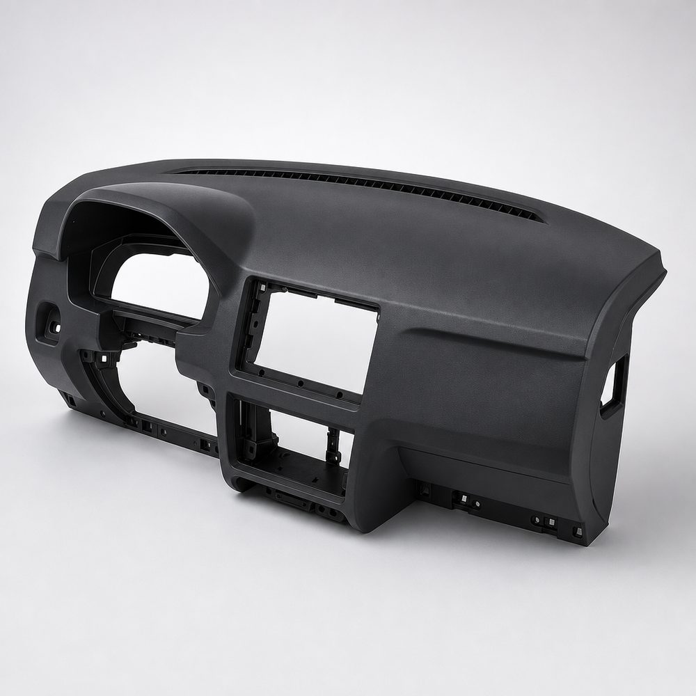
Warpage, Ribs and the Visible Surface
Wall Thickness Uniformity
Rib Proportion and Sink
Gate Location and Weld Lines
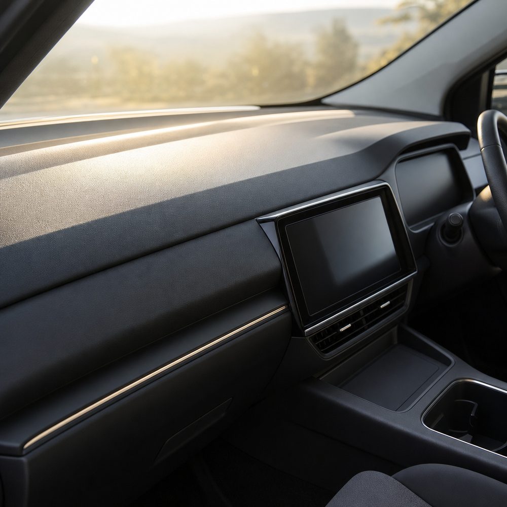
Specification Envelope for a Dashboard Plastic Shell
Parameter Typical envelope Why it drives the result Material PC/ABS or ABS, interior grade Heat and impact balance, plus colour stability Nominal wall 2.0-3.0 mm Uniform wall limits shrinkage imbalance and warpage Rib thickness 0.5-0.6 of nominal wall Controls sink on the visible surface Draft 1 degree or more on textured walls Prevents drag marks on release Tolerance Per drawing GD&T, ISO 2768-m as a base Appearance and assembly both depend on it Surface Texture per customer grain standard Hides flow marks, sets the gloss target Warpage Flatness verified on a fixture after 24 h Parts move after demoulding; measure later, not at the press Heat, Odour and Service Assembly
Heat Ageing and Colour Shift
Odour and Interior Emissions
Clips, Bosses and Repeated Service
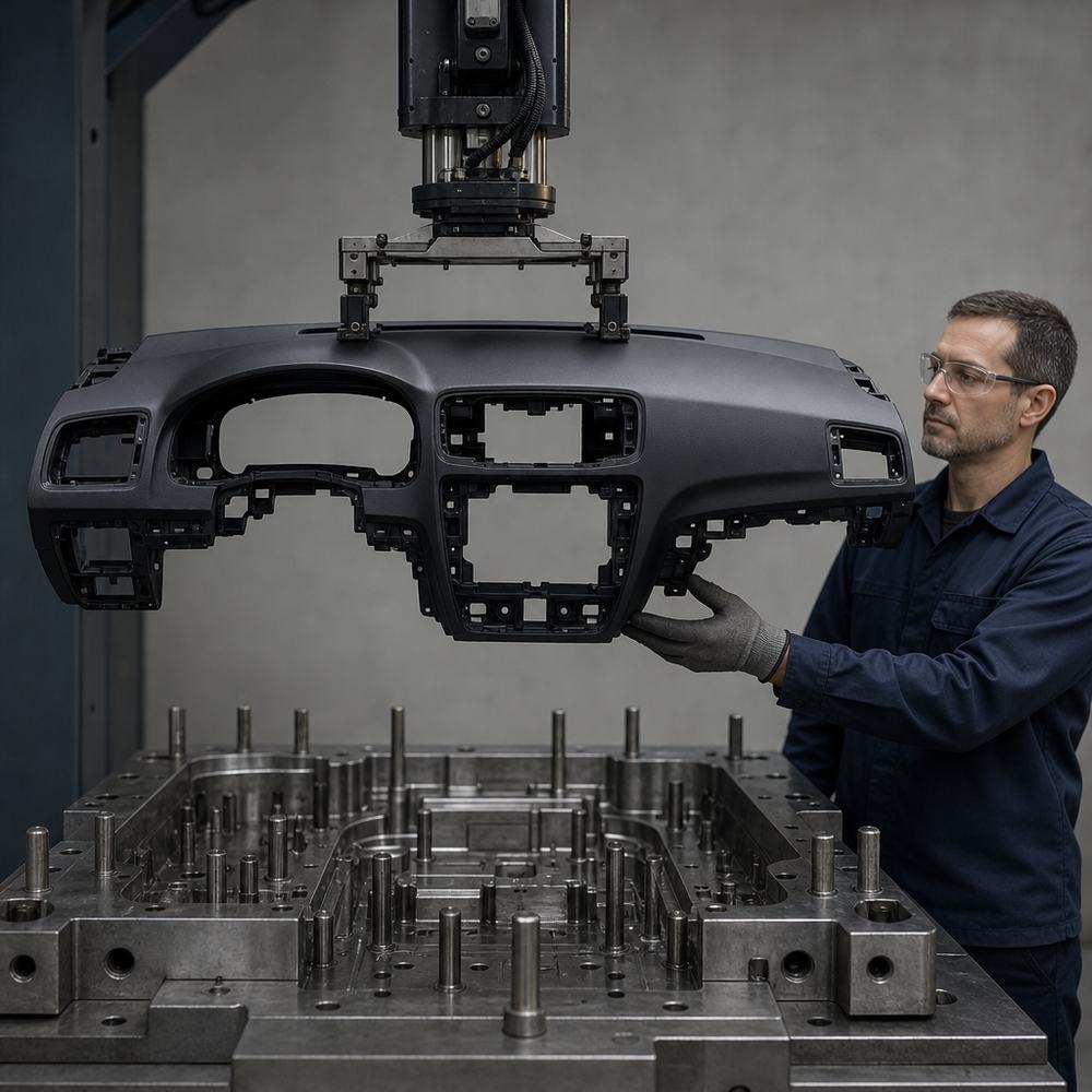
Tooling, First Article and Production Control
Mould Flow Before Steel
Tool Steel, Cavitation and Cooling
First Article and Run-at-Rate
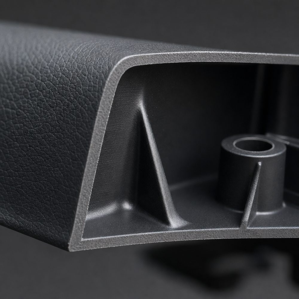
Dashboard Shell Questions From Buyers
Can you mould a class-A visible surface?
Why does the part warp even when dimensions are in tolerance?
Do you support low-volume programmes?
Send the 3D Data and the Appearance Standard