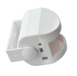
Fireproof USB Charger Enclosure New Multi-port USB Splitter Housing
- Model
- BH-Plastic Enclosure
Item specifics
- Design
- Follow 3D Drawing Or Physical Object
- Process
- Injection Molding
- Feature
- Multi-port,reliable
- MOQ
- 1000pcs
- Application
- USB Charger
Review
Description
Fire-rated power enclosures Three things decide whether a multi-port charger housing is safe: what the plastic does after it ignites, what stands between mains and the low-voltage side, and where the heat actually goes. This enclosure answers all three — UL94 V-0 polycarbonate, a 3 mm internal fire barrier, and a metal path from the PCB to the outside. V-0 is a flame-spread rating, not a promise that nothing burns. What it buys is time and containment: the compound self-extinguishes, and the polycarbonate forms a char layer that keeps the flame away from what is behind it. The oxygen index of this grade is above 32, and the flame-retardant package is halogen-free — relevant if your end customer is working to a halogen-free procurement policy. What it does not buy is thermal design. A V-0 housing that traps heat will still fail a temperature-rise test, and no material rating rescues a layout where the GaN stage has nowhere to dump its losses. The mains compartment is physically separated from the DC output side by an internal 3 mm wall moulded from the same V-0 material. It is not a coating and not a secondary part, so it cannot be left out on the line. The electrical layout is designed around a 250 VAC input: creepage and clearance of 6 mm or more, integrated grounding posts, and a moulded slot for the fuse holder. If you are working through a 62368-1 assessment, that is the part of the drawing the reviewer will ask for first. The PCB mounts directly onto an aluminium plate, and that plate contacts thermal pads moulded into the exterior base. The result is a continuous metal path from the switching devices to the outside face instead of a plastic box full of warm air. Combined with vent grilles at roughly 45 % open area, our measurements on this platform show hotspot temperatures up to 40 % lower than an equivalent passive housing. The mould is modular. The standard build carries four USB-C PD 3.1 ports plus two USB-A QC 3.0 ports; two- to six-port arrangements are handled with inserts rather than a new tool, which is what keeps a 65 W and a 140 W variant on the same platform economics. Housings are rarely rejected for the plastic. They are rejected because the creepage distance was drawn at 5 mm, or because the fuse was placed where a service technician could reach it. We keep the material certificates, the UL card and the wall-thickness data with the tool record, so the package you hand to the test lab is the package that matches the parts you are shipping. A housing is quoted from the PCB and the port plan. Send both and the reply is a shell proposal with the barrier, vent and heatsink layout marked on it. Dongguan Bohao Electronic Technology Co., Ltd. IATF 16949:2016 / ISO 9001:2015 certified. Values shown are typical for the listed compound or platform; the drawing and the approved sample govern production.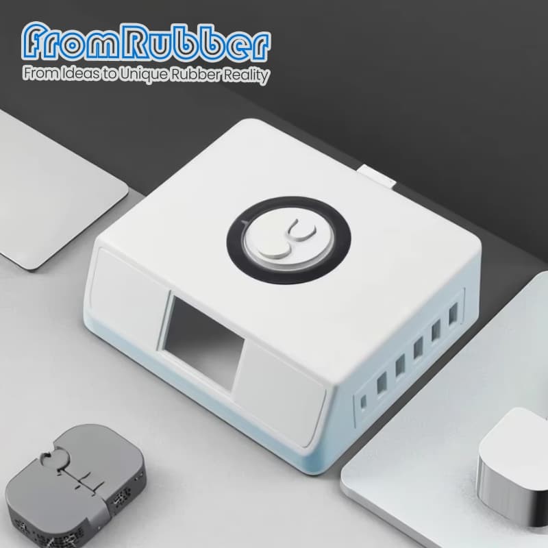
A fireproof multi-port charger enclosure is a material, a barrier and a heat path
What V-0 buys, and what it does not
The 3 mm barrier is the part engineers ask about
Where the heat goes
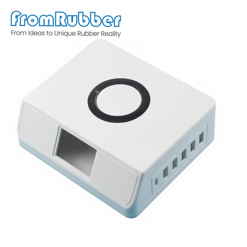
Port architecture
Parameter Value on this platform Shell material V-0 polycarbonate, PA66-GF30 for structural parts Fire rating UL94 V-0, oxygen index above 32, halogen-free Wall thickness 2.5 mm in critical areas Electrical 250 VAC input, creepage and clearance 6 mm or more Thermal Aluminium heatsink plate, 45 % open vent area Ingress IP40, dust protection for indoor equipment Finishing Pantone colour matching, logo emboss or deboss, cable management Certification starts at the drawing
How the project runs
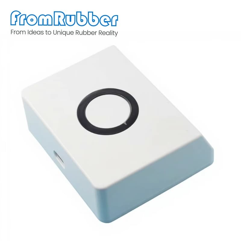
What we need to quote
What comes back
Send the board outline, not a photo
fromrubber.com
+86 18926836960