


Power Adapter Housing Multi-port Type C Charger Plastic Shell
- Model
- BH-Plastic Enclosure
Item specifics
- Design
- Follow 3D Drawing Or Physical Object
- Process
- Injection Molding
- Feature
- Multi-port,reliable
- MOQ
- 1000pcs
- Application
- Power Adapter
Review
Description
GaN charger housings A charger shell is not a box around a PCB. The wall thickness sets the creepage, the vent pattern sets the hotspot, and the joint decides whether the line needs screws. This platform is sized for 65 W, 100 W and 140 W GaN layouts: 78 × 58 × 32 mm, PC/ABS V-0, 1.8 mm nominal wall. Almost every cost argument on a charger housing comes down to the same three choices, and all three are made at the drawing stage: Internal ribs are placed to carry the PCB and to break the air volume into channels, and the convection vents sit above the hottest devices rather than where they look symmetrical. On this platform that arrangement is worth up to 15 % lower operating temperature against a closed shell of the same volume, which is usually the difference between passing a temperature-rise test at nominal load and derating the output. The material runs a comparative tracking index above 400 V, which matters in humid markets. Moulded ridges take an EMI gasket, and the internal contact points are positioned so the PCB ground plane meets the shell where the shield needs it — details that are cheap in the tool and expensive as a running change. Where a strain relief is needed, a two-shot process combines rigid PC for the body with a flexible TPE boot. The folding-plug mechanism on this platform is designed for 10,000 cycles. The same shell serves desktop chargers, travel adapters and docking power modules, because the port inserts change without changing the outer tool. If your product also has to survive dust and splash, the fireproof enclosure platform uses the same V-0 material family with an internal barrier; if the requirement is really a sealed joint, the IP65 to IP68 rating guide explains what has to change in the drawing. Shells are quoted from the board outline. Send it with the wattage and the port count and we will come back with a shell proposal and a tooling plan. Dongguan Bohao Electronic Technology Co., Ltd. IATF 16949:2016 / ISO 9001:2015 certified. Values shown are typical for the listed compound or platform; the drawing and the approved sample govern production.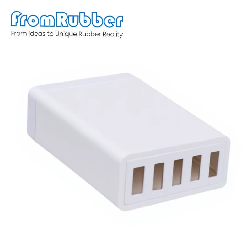
A multi-port Type-C charger shell is designed around the board inside it
Three decisions that set the unit cost
The thermal path
EMI and grounding are moulded in
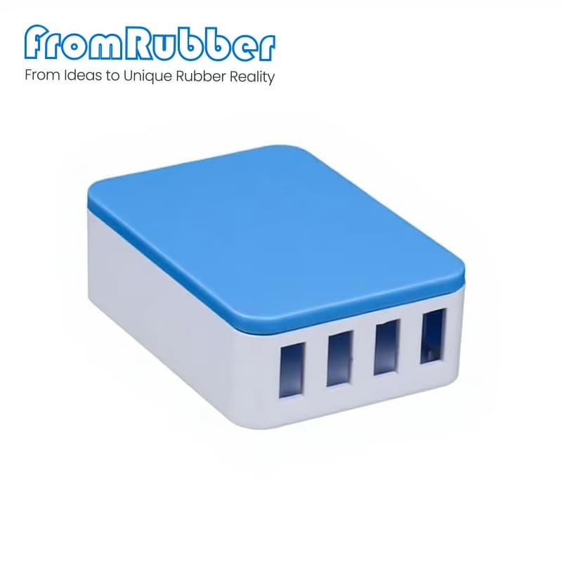
Parameter Value on this platform Material Flame-retardant PC/ABS, UL94 V-0 Wall thickness 1.8 mm nominal Envelope 78 × 58 × 32 mm, four-port variant Ports 2× USB-C PD + 2× USB-A, or 4× USB-C Board fit 65 W, 100 W and 140 W GaN layouts Creepage 8.5 mm, supports 240 V design Assembly Snap-fit plus sonic-weld ribs, screws optional Finish Matte white, space grey, gloss black, any Pantone One platform, several products
How the project runs
What we need to quote
What comes back
Send the GaN board and the port mix
fromrubber.com
+86 18926836960


