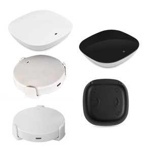
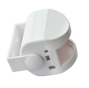
Plastic Enclosures for PCB, Sensors & Wireless Devices
- Model
- BH-Plastic Enclosure
Item specifics
- Design
- Follow 3D Drawing Or Physical Object
- Process
- Molding
- Feature
- Tailored for multiple purposes
- MOQ
- 1000pcs
- Application
- electronic modules, sensors, and wireless decices
Review
Description
For a wired product the housing is mechanical protection. For a wireless one it is also an electrical component: every millimetre of plastic between the antenna and the outside world, every coat of paint and every screw boss near the radiator changes the match. That is why a housing that looks correct on a drawing can cost 10 dB of range in the field, and why the antenna layout has to be settled before the tool is cut. The same logic applies to sensors. A temperature or humidity sensor inside a sealed box measures the inside of the box, not the room. The aperture - its size, its position and the mesh behind it - is the sensor's actual interface. Leave the wall in front of the antenna as thin and as plain as the structure allows, with no rib, boss or label directly over the radiator. If a decorative part must sit there, make it a separate, replaceable piece. Aperture area, depth and any mesh decide response time and dust ingress together. A deep, narrow aperture protects the sensor and slows it down; a wide, shallow one responds quickly and passes dirt. The distance between board and wall is fixed by the standoffs, and it decides both the antenna clearance and whether the tallest component fouls the lid. Specify the gap, not just the board outline. Conductive paint, vacuum metallising and carbon-loaded compounds are legitimate choices for EMC - and they are the fastest way to kill a radio link if they end up in front of the antenna. Mark the antenna zone on the drawing and state that it must stay uncoated. Thickness helps stiffness at the corners and around the screw fixings, and it helps impact resistance where the product lands. It does not help the radio, and it does not help weight. Keep the wall nominal across the antenna area and put the material where the loads are. Ribs are the cheaper way to stiffness: they add section without adding a thick wall, and they avoid the sink marks that a heavy wall leaves on the visible face. Housing design for a general electronic product is covered in PCB enclosure materials. If the box has to be fixed to a wall, the mounting pattern becomes the main question - see enclosures with mounting holes. If it has to survive immersion, see the IP67 junction box. It can, and the mechanism is detuning rather than simple attenuation: plastic close to the antenna shifts its resonant frequency and changes the match. The fix is clearance and a clean window, verified by measuring the antenna inside the real housing. Yes, as an insert or a printed or plated structure, but then the housing and the radio have to be designed together. It saves assembly time and removes a connector, at the cost of a much less flexible tool. Big enough to give the response time the product claims, small enough to keep dust and water out. Start from the sensor's own recommended opening and then test the assembly; the housing changes the answer. It depends on what is inside and where the product is sold. If the answer is yes, say so before tooling: flame-retardant grades flow differently and can change gate position and wall thickness. Antenna clearance, aperture size and standoff height are settled on the first drawing, not after the tool is cut. Send the PCB outline with the antenna and sensor locations marked, and we will return a housing proposal with those zones resolved.A plastic enclosure for a wireless device is part of the antenna, not a box around it

Three interfaces the housing must respect
Antenna window
Keep material out of the near field
Sensor aperture
A hole is a design element
PCB mounting
Standoffs set the gap
Material choice is a radio decision as well as a mechanical one
Wall thickness, ribs and the parts that are easy to get wrong
Where thickness helps
Where it goes wrong
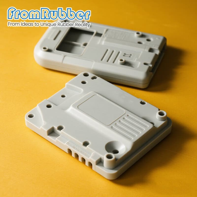
Specification on this series
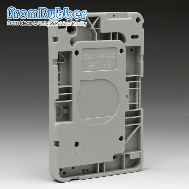
Questions from hardware teams
Will a plastic housing reduce my wireless range?
Can the antenna be moulded into the housing?
How big should a sensor aperture be?
Do I need a flame-retardant grade?
Send the board and the antenna position